DA-98
Important Safety Precautions
Important Safety Instructions
Introduction to the DA-98
Rear Panel connectors
Table of Contents
Front Panel controls
Synchronization with other Dtrs units
Table of Contents Monitoring modes
Advanced operations
Operations related to timecode
Maintenance and memory setups
Table of Contents Menu and parameter reference
Example setups
Options, specifications and reference
TOC-4 1.00 06/97
Introduction to the DA-98
Features
Unpacking
Clock source in a digital studio
Using this manual
Precautions and recommendations
Confidence replay
Electrical considerations
Installing the DA-98
Environmental conditions
Condensation
Recommended tapes
Tape brands
Available recording and playback time
Introduction to the DA-98
Front Panel controls
Auto Play F 4 key and indicator
Rhsl F 1 key and indicator
Auto Punch F 2 key Indicator
Digital in switch and indicator
LOC 2 Preset key
Shtl MON F 8 key and indicator
Repeat F 9 key and indicator
Shift key and indicator
FWD key
Front Panel controls TC REC switch and indicator
REW key
Stop key
40 RS-422
Rear Panel connectors
Time Code in and OUT
Meter Unit MU-8824
Rear Panel connectors
Audio connections
Connections
Synchronization connections
Control connections
1 RS-422 connector
Midi connectors in , OUT and Thru
Word clock connections
Multiple Dtrs units
Connection to other Tascam units
Parallel control
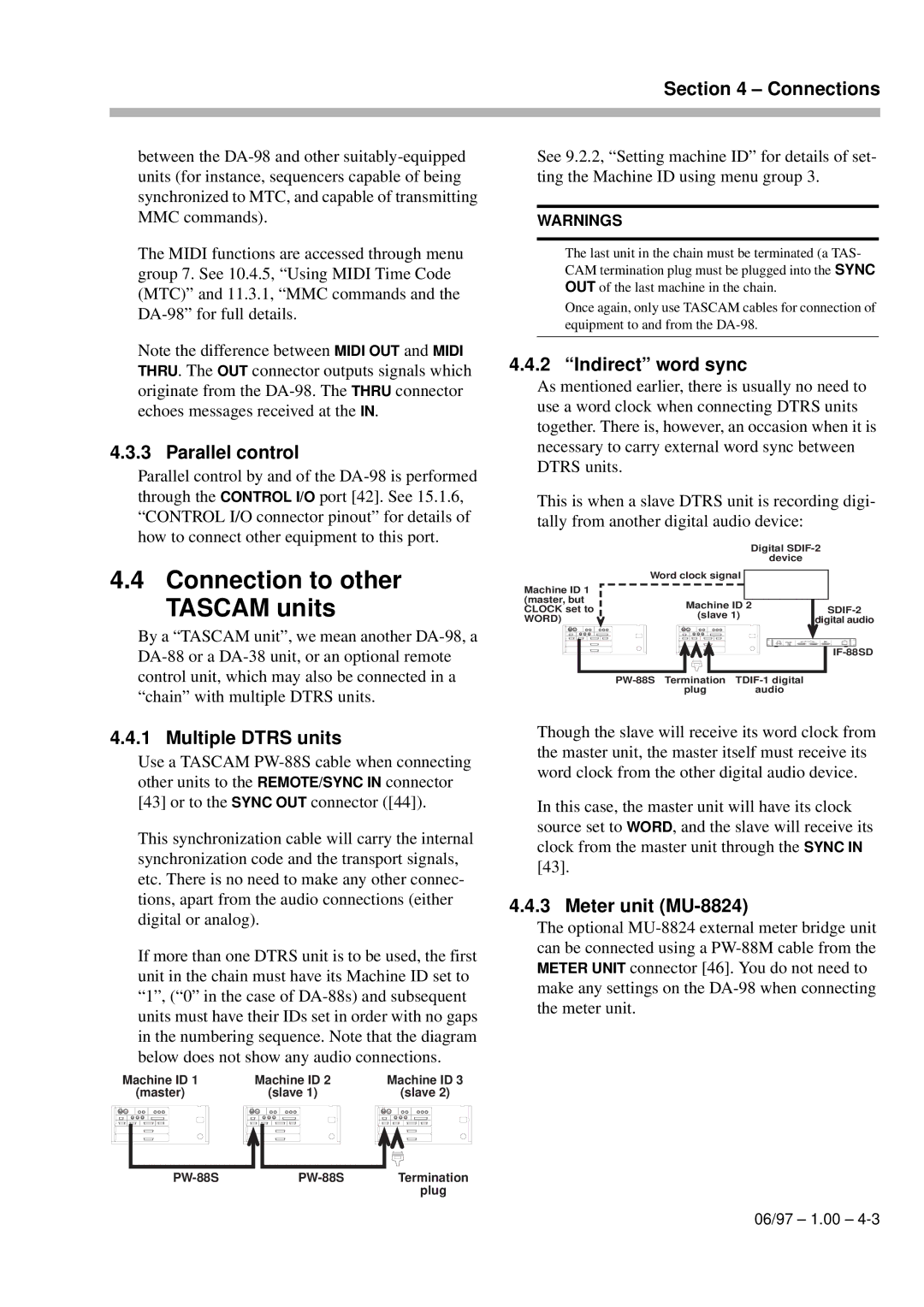
Indirect word sync
Connections
Menu operations
Menus
Changing menu values fast
Resetting a menu value
FunctionFunctionkey modes
Blanking the screen display
Shift key and function keys
Recalling an assigned menu function
Assigning menus to function keys
To assign a menu screen to a key
PressLothecaFt5e0key1Pm13rien-0r5oslelc
Aborting the format process
Basic operations
Formatting a tape
Threaded, the tape counters will show
Recording while formatting
Recording the first tracks
Preparing to record
Write-protecting cassettes
Punch-in and punch-out
Overdubbing
Track bouncing
Replaying the first tracks
At the point where the punch is to occur, press
Automatic punch point setting
Setting punch points on the fly
At the point where you want to punch out, press Play
Basic operations Editing the pre-roll and post-roll times
Setting punch points using the menus
Press Escape to re urn to menu group
Interrupting a rehearsal or punch recording
Rehearsing the punch-in
Recording the punch-in
Replaying the punched material
Exiting punch-in mode
Press the Auto MON key so that the indicator goes out
To replay the punch-in, press the Play key
Basic operations
ALL Input 18 and Input Monitor
Monitoring modes
Monitoring controls
Auto MON
Confidence mode
Monitoring modes Shuttle monitoring
Arming tracks in pairs
Using confidence mode
To leave confidence mode, press
Monitoring modes
Advanced operations Autolocation
Setting Memo 1 and Memo 2 on the fly
Setting the location pre-roll time
Checking, editing and manually entering Memo 1 and Memo
Editing function key memories
Press the LOC 2/PRESET key
Moving to Memo 1 and Memo
Pr ss Enter
To start repeat play
Locating to a function key memory
Repeat function
Location and playback
Crossfade times
Track delay
Press the Enter key
Shuttle operations
Use the UP and Down keys to adjust the crossfade time
Vari speed pitch control
Press Enter
LevelEnter m nu
Reference levels
Shuttle muting
Use the UP and Down keys to select between
Sine oscillator
Keys to set the value for the peak signal level hold time
Meter modes
Advanc d operations Meter ballistics
Changing between digital and analog inputs
Digital recording
Routing digital inputs
Selecting word length
REC Mute recording silence
Dither
Setting the power-on message
Lecting dither settings
Synchronization with other Dtrs units
Machine ID and master/ slave settings
Differences between Dtrs models
Offset +00
Setting mac ne ID
Machine offset
Ing machine offset
Setting machine On the fly
Cancelling machine offset
An example of setting offsets
Digital dubbing
Start playing the master DA-98
Synchronized formatting
On the master machine, hold down Record and press Play
Synchronization with other Dtrs units
ABS time
Operations related to timecode
ABS and SMPTE/EBU timecode
Tape timecode
TcTrack setting
Tape timecode mode
Location point settings
ABS setting
ABS-13 and ABS-23 settings
Checking tapeTCTrack
Pull up and pull down Fs shift
Selecting the frame rate
Timecode input and output
Timecode input
Timecode output format
Timecode output
Timecode output timing
Recording timecode
Using Midi Time Code MTC
Recording timecode using the generator
Selecting the timecode source
Select a frame rate see 10.3, Selecting
Press the TC REC switch
10.1.3, Sele ting TC or ABS timing
Frame rate
External timecode sources
Menu see 10.2.1, TcTrack setting
Assembling timecode
Start playing the tape
When recording timecode from a digital source
When recording timecode from a timecode
When recording timecode from another Dtrs
When recording timecode from an analog
Checking external timecode
Video resolution
Chasing to timecode
Machine ID and timecode
Cancelling timecode offset
Setting timecode offset
SectionOffset10 Operations related to timecode
Absolute and relative difference
Automatic park position setting
Park position
Play the timecode master
10.7.10Bypassing timecode errors
Rechasing timecode
10-14 1.00 06/97
Use with 9-pin external control
Record delay
External control
Pro oc
Fast wind speed
Cue-up tally
Still
Timecode track mapping
Track mapping
Tr k mapping and press Enter
Bus protocol
Midi Machine Control
Midi
11-6 1.00 06/97
Menu and parameter reference Menu groups
Menu group
Menu and parameter
Ference
ErrBypass
OutTcSrcTapeTC
Menu and parameter Refe ence
TrkMapCueupTly
Section
Stop
12.1.10Menu group
12.1.11Menu group E
12.1.12Menu group F
ArkPsition
Menu item ind
Example setups
An all-DA-98 setup
Post-production work
Example setups
Project studio ‘B’ room
Example setups
13-6 1.00 05/30/97
Maintenance and memory setups Head and transport cleaning
To c ean he heads and transport
Checking error rates
Checking head time
User setups
Saving user setups
Software upgrades
Resetting the memory
Checking version
Remote control RC-848
Options, specifications and reference Options for the DA-98
15.1.1 RM-98 Rack Mount Adaptor
Digital audio convertors
Control I/O connector pinout
Cables
Power specifications
Specifications
Physical specifications
Digital recording characteristics
Audio specifications Inputs and outputs
Options, specifications and reference Tape transport
15.2.8 9-pin RS-422, MIDI, synchronizer specifications
Options, specifications and reference
MMC Bit Map Array
SYS. MAS
15-7 1.00 06/97
Midi Implementation Chart
Midi
Index
BER
Index-10 1.00 06/97
06/97 1.00 Index-11
Index-12 1.00 06/97
DA-98