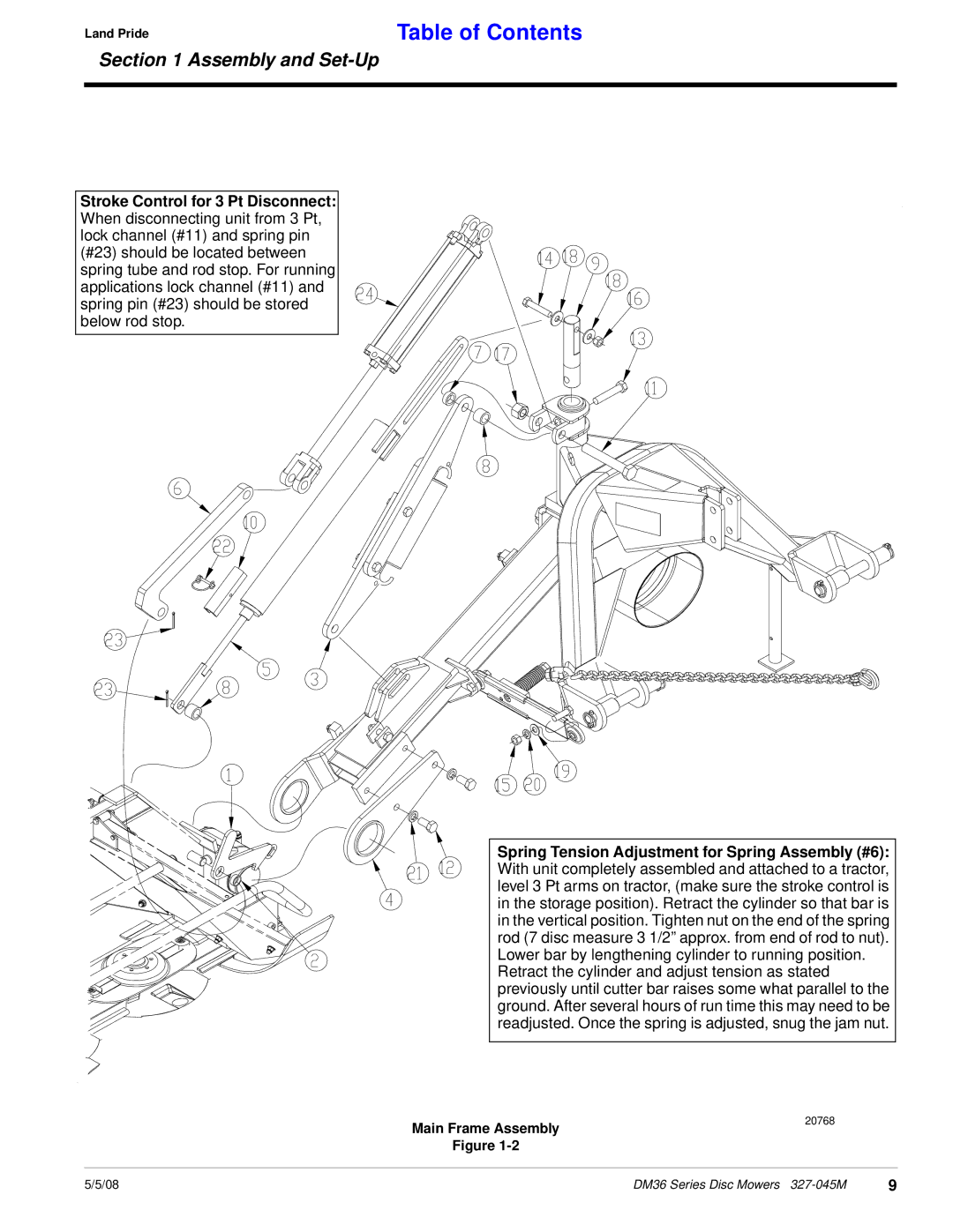
DM36 Series specifications
The Land Pride DM36 Series is a premium line of rotary mowers designed for durability, efficiency, and exceptional performance in demanding mowing conditions. These mowers are engineered to provide precise cutting and maintenance for a variety of environments, making them ideal for both professional landscapers and property owners seeking a reliable mowing solution.One of the standout features of the DM36 Series is its heavy-duty construction. Built with a robust steel chassis, the mower is designed to withstand the rigors of frequent use while providing stability and control. The reinforced deck is fully welded, ensuring that it can handle rough terrain and obstacles without compromising its structural integrity.
The DM36 Series also boasts adjustable cutting heights ranging from 1 to 4 inches, allowing operators to customize their mowing experience based on the type of vegetation and field conditions. This versatility is complemented by the mower's efficient blade design, which includes high-quality blades specifically designed to create a clean cut and minimal discharge, resulting in a tidy appearance and healthier turf.
Equipped with advanced technology, the DM36 Series incorporates features that enhance operational efficiency. The mower is designed for compatibility with various tractors, allowing for smooth integration with existing equipment. Additionally, its quick-attach mounting system ensures easy installation and removal, streamlining the workflow for users.
For improved operator comfort, the DM36 series includes ergonomic handles and controls that are strategically placed for ease of use. The mower's design reduces vibration and noise, promoting a more enjoyable mowing experience, especially during extended use.
Another notable characteristic of the DM36 Series is its maintenance-friendly design. Regular servicing and maintenance are simplified thanks to accessible grease points and easily replaceable parts. This approach not only extends the life of the mower but also ensures it remains in top working condition with minimal downtime.
In summary, the Land Pride DM36 Series combines robust construction, adjustable cutting heights, advanced technology, and user-friendly design to provide an exceptional mowing experience. Whether you're maintaining large properties, parks, or commercial landscapes, the DM36 Series stands out as a trusted and effective solution for all mowing needs. With its commitment to quality and performance, Land Pride continues to be a leader in the rotary mower market.

