3.6 Integrated Peripherals Setup
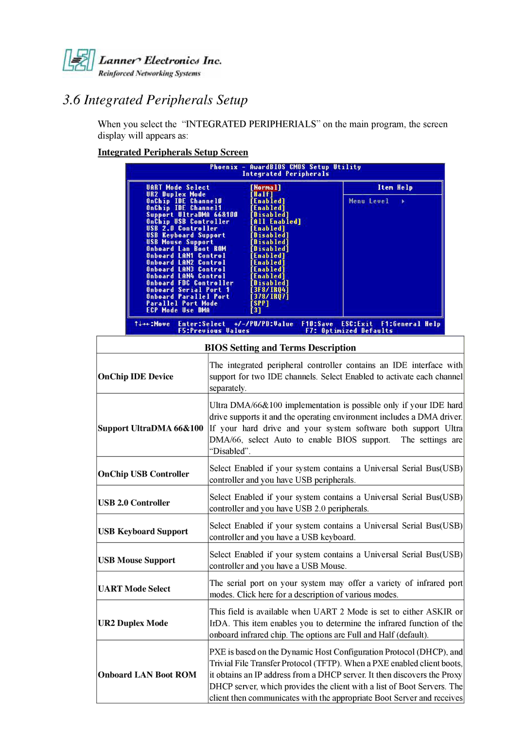
When you select the “INTEGRATED PERIPHERIALS” on the main program, the screen display will appears as:
Integrated Peripherals Setup Screen
| BIOS Setting and Terms Description | |
OnChip IDE Device |
| The integrated peripheral controller contains an IDE interface with |
| support for two IDE channels. Select Enabled to activate each channel | |
|
| separately. |
|
| Ultra DMA/66&100 implementation is possible only if your IDE hard |
Support UltraDMA 66&100 |
| drive supports it and the operating environment includes a DMA driver. |
| If your hard drive and your system software both support Ultra | |
|
| DMA/66, select Auto to enable BIOS support. The settings are |
|
| “Disabled”. |
OnChip USB Controller |
| Select Enabled if your system contains a Universal Serial Bus(USB) |
| controller and you have USB peripherals. | |
|
| |
USB 2.0 Controller |
| Select Enabled if your system contains a Universal Serial Bus(USB) |
| controller and you have USB 2.0 peripherals. | |
|
| |
USB Keyboard Support |
| Select Enabled if your system contains a Universal Serial Bus(USB) |
| controller and you have a USB keyboard. | |
|
| |
USB Mouse Support |
| Select Enabled if your system contains a Universal Serial Bus(USB) |
| controller and you have a USB Mouse. | |
|
| |
UART Mode Select |
| The serial port on your system may offer a variety of infrared port |
| modes. Click here for a description of various modes. | |
|
| |
UR2 Duplex Mode |
| This field is available when UART 2 Mode is set to either ASKIR or |
| IrDA. This item enables you to determine the infrared function of the | |
|
| onboard infrared chip. The options are Full and Half (default). |
|
| PXE is based on the Dynamic Host Configuration Protocol (DHCP), and |
Onboard LAN Boot ROM |
| Trivial File Transfer Protocol (TFTP). When a PXE enabled client boots, |
| it obtains an IP address from a DHCP server. It then discovers the Proxy | |
|
| DHCP server, which provides the client with a list of Boot Servers. The |
|
| client then communicates with the appropriate Boot Server and receives |
