| the name of the boot image. The client uses TFTP to download the | |
| Network Bootstrap Program (NBP) from the Boot Server and then | |
| initiates execution of the image (boots from the image). | |
Onboard |
| |
LAN1/LAN2/LAN3/LAN4 | Enable your LAN Controller | |
Control |
| |
On board FDC Controller | Enable the onboard floppy controller. Select Enabled when you have | |
installed a floppy disk drive. | ||
| ||
Onboard Serial Port 1 | Select an address and corresponding interrupt for the first and second | |
serial ports. The settings are “3F8/IRQ4”, “2E8/IRQ3”, “3E8/IRQ4”, | ||
| “2F8/IRQ3”, “Disabled”, “Auto”. | |
Onboard Parallel Port | This item allows you to determine onboard parallel port controller I/O | |
address setting. The settings are “378H/IRQ7”, “278H/IRQ5”, | ||
| “3BC/IRQ7”, “Disabled”. | |
Parallel Port Mode | Select an operating mode for the onboard parallel (printer) port. Select | |
“Normal”, “Compatible”, or “SPP” unless you are certain your hardware | ||
| and software both support one of the other available modes. | |
ECP Mode Use DMA | Select a DMA channel for the parallel port for use during ECP mode. | |
The settings are “3” and “1” | ||
|
3.7 Power Management Setup
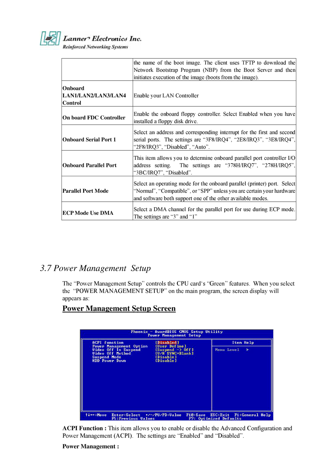
The “Power Management Setup” controls the CPU card‘s “Green” features. When you select the “POWER MANAGEMENT SETUP” on the main program, the screen display will appears as:
Power Management Setup Screen
ACPI Function : This item allows you to enable or disable the Advanced Configuration and Power Management (ACPI). The settings are “Enabled” and “Disabled”.
