1.4.3 Jumper Settings and I/O Connector
The onboard jumper settings and I/O connector of
Jumper Settings and I/O Connector Summary for
JUMPER | FUNCTION |
CMOS1 | Clear CMOS Data |
PLRS1 | Power LED,HD LED, Reset, Speaker Connector(11 Pin 2.54mm) |
FAN1 | 3 Pin Fan Connector |
LAN Connector | |
PRJK1 | 3 Pin Power Input Jack |
COMA1 | |
PKMB1 | PS/2 Keyboard & Mouse Connector |
VGAB1 | External VGA Connector ( Header ) |
LPTA1 | Parallel Connector |
USBB1 | Dual USB Connector |
CF1 | Compact Flash Connector |
IDEB1 | IDE Interface Connector |
PCIB1 | 124 Pin Mini PCI Socket |
1.4.4 Connector Pin Assignments
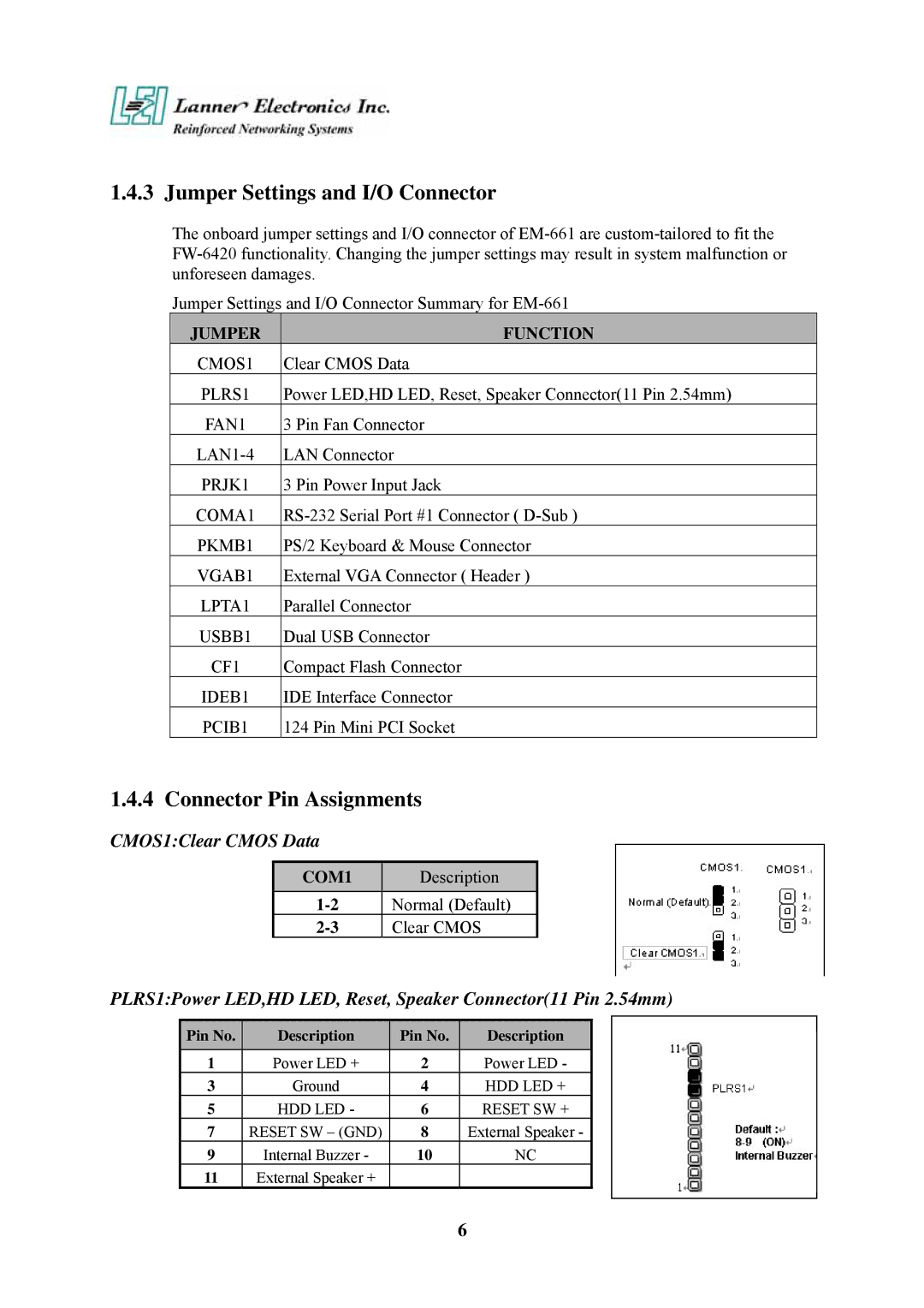
CMOS1:Clear CMOS Data
COM1 | Description |
Normal (Default) | |
Clear CMOS |
PLRS1:Power LED,HD LED, Reset, Speaker Connector(11 Pin 2.54mm)
Pin No. | Description | Pin No. | Description |
1 | Power LED + | 2 | Power LED - |
3 | Ground | 4 | HDD LED + |
5 | HDD LED - | 6 | RESET SW + |
7 | RESET SW – (GND) | 8 | External Speaker - |
9 | Internal Buzzer - | 10 | NC |
11 | External Speaker + |
|
|
6