10
Step 3. INSTALL THE VENT SYSTEM
General Information
These instructions should be used as a guide- line and do not supersede local codes in any way. Install vent according to local codes, these instructions, the current National Fuel Gas Code
These fireplaces are designed, tested and listed for operation and installation with, and only with, Secure Vent™ Direct Vent System Components, Secure Flex™
Flexible Vent Components manufactured by Security Chimneys International and
These fireplaces must be vented directly to the outside.
Determine the venting for the appliance. If the vent run will include at least 8 feet of vertical rise, then install the second restrictor in the appliance collar before connecting any vent (Refer to Figure 12 ). Place the second restric- tor inside the fixed restrictor.
Note: The second restrictor is included within the firebox.
Exhaust Vent | Fixed Restrictor |
Second Restrictor (For Vertical Vent Only)
Figure 12
The vent system may not service multiple appliances, and must never be connected to a flue serving a solid fuel burning appliance. The vent pipe is tested to be run inside an enclos- ing wall (such as a chase). There is no require- ment for inspection openings in the enclosing wall at any of the joints in the vent pipe.
Select Venting System - Horizontal or Vertical
With the appliance secured in framing, deter- mine vent routing and identify the exterior termination location. The following sections describe vertical (roof) and horizontal (exterior wall) vent applications. Refer to the section relating to your installation. A list of approved venting components is shown in the tables on page 26.
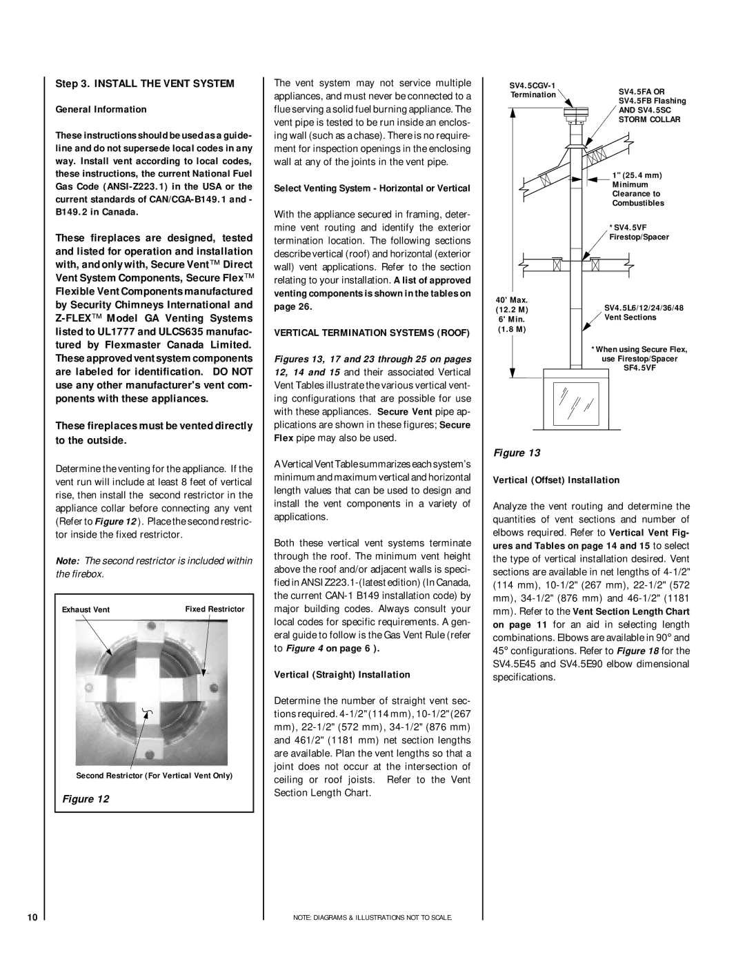
VERTICAL TERMINATION SYSTEMS (ROOF)
Figures 13, 17 and 23 through 25 on pages 12, 14 and 15 and their associated Vertical Vent Tables illustrate the various vertical vent- ing configurations that are possible for use with these appliances. Secure Vent pipe ap- plications are shown in these figures; Secure Flex pipe may also be used.
A Vertical Vent Table summarizes each system’s minimum and maximum vertical and horizontal length values that can be used to design and install the vent components in a variety of applications.
Both these vertical vent systems terminate through the roof. The minimum vent height above the roof and/or adjacent walls is speci- fied in ANSI
Vertical (Straight) Installation
Determine the number of straight vent sec- tions required.
NOTE: DIAGRAMS & ILLUSTRATIONS NOT TO SCALE.
SV4.5FA OR | ||
Termination | ||
SV4.5FB Flashing | ||
| ||
| AND SV4.5SC | |
| STORM COLLAR |
1" (25.4 mm) Minimum Clearance to Combustibles
*SV4.5VF Firestop/Spacer
40' Max. |
|
|
| SV4.5L6/12/24/36/48 | |||||
(12.2 M) |
|
|
| ||||||
|
| ||||||||
6' Min. |
|
|
| Vent Sections | |||||
(1.8 M) |
|
|
|
|
|
| |||
|
|
|
|
|
| *When using Secure Flex, | |||
|
|
|
|
|
|
| use Firestop/Spacer | ||
|
|
|
|
|
|
|
|
| SF4.5VF |
|
|
|
|
| |||||
|
|
|
|
|
|
|
|
|
|
|
|
|
|
|
|
|
|
|
|
|
|
|
|
|
|
|
|
|
|
|
|
|
|
|
|
|
|
|
|
Figure 13
Vertical (Offset) Installation
Analyze the vent routing and determine the quantities of vent sections and number of elbows required. Refer to Vertical Vent Fig- ures and Tables on page 14 and 15 to select the type of vertical installation desired. Vent sections are available in net lengths of