IMPORTANT: Ground supply lead must | Gas Line Access Plate Not Installed |
|
| |||||
be connected to the wire attached to the |
|
| ||||||
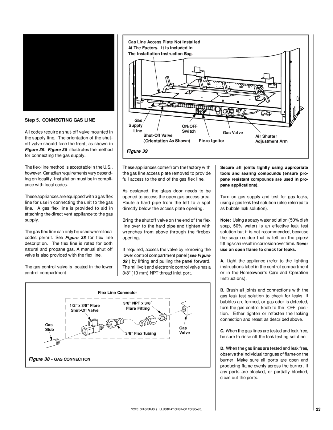
At The Factory. It Is Included In |
|
|
| |||||
green ground screw located on the out- | The Installation Instruction Bag. |
|
|
| ||||
let box. See Figure 37. Failure to do so |
|
|
|
|
| |||
will result in a potential safety hazard. |
|
|
|
|
| |||
The appliance must be electrically |
|
|
|
|
| |||
grounded in accordance with local codes |
|
|
|
|
| |||
or, in the absence of local codes, the |
|
|
|
|
| |||
National Electrical Code, ANSI/NFPA 70- |
|
|
|
|
| |||
(latest edition). (In Canada, the current |
|
|
|
|
| |||
CSA |
|
|
|
|
| |||
Step 5. CONNECTING GAS LINE | Gas |
|
|
|
| |||
|
|
| Supply | ON/OFF |
|
|
| |
All codes require a | Line | Switch |
| Gas Valve | Air Shutter | |||
the supply line. The orientation of the shut- |
| Piezo Ignitor | ||||||
(Orientation As Shown) | Adjustment Arm | |||||||
off valve should face the front, as shown in | ||||||||
|
|
|
|
| ||||
Figure 39. Figure 38 illustrates the method | Figure 39 |
|
|
|
| |||
for connecting the gas supply. |
|
|
|
|
| |||
The | These appliances come from the factory with | Secure all joints tightly using appropriate | ||||||
however, Canadian requirements vary depend- | the gas line access plate removed to provide | tools and sealing compounds (ensure pro- | ||||||
ing on locality. Installation must be in compli- | full access to the end of the gas flex line. | pane resistant compounds are used in pro- | ||||||
ance with local codes. | As designed, the glass door needs to be | pane applications). | ||||||
These appliances are equipped with a gas flex |
|
| ||||||
opened to access the open gas access area. | Turn on gas supply and test for gas leaks, | |||||||
line for use in connecting the unit to the gas | Route a hard pipe from the left to a spot | using a gas leak test solution (also referred to | ||||||
line. | A gas flex line is provided to aid in | directly below the access plate opening. | as bubble leak solution). | |||||
attaching the direct vent appliance to the gas |
|
|
|
|
| |||
supply. |
| Bring the shutoff valve on the end of the flex | Note: Using a soapy water solution (50% dish | |||||
The gas flex line can only be used where local | line over to the hard pipe and tighten with | soap, 50% water) is an effective leak test | ||||||
wrenches from above through the firebox | solution but it is not recommended, because | |||||||
codes permit. See Figure 38 for flex line | opening. |
|
| the soap residue that is left on the pipes/ | ||||
description. | The flex line is rated for both |
|
|
| fittings can result in corrosion over time. Never | |||
natural and propane gas. A manual shut off | If required, access the valve by removing the | use an open flame to check for leaks. | ||||||
valve is also provided with the flex line. | lower control compartment panel (see Figure | A. Light the appliance (refer to the lighting | ||||||
|
|
| 39 ) by lifting and pulling the panel forward. | |||||
The gas control valve is located in the lower | The millivolt and electronic control valve has a | instructions label in the control compartment | ||||||
control compartment. | 3/8" (10 mm) NPT thread inlet port. |
| or in the Homeowner's Care and Operation | |||||
|
|
|
|
|
| Instructions). |
| |
|
| Flex Line Connector |
|
| B. Brush all joints and connections with the | |||
|
|
|
| gas leak test solution to check for leaks. If | ||||
|
|
|
|
|
| |||
|
| 1/2" x 3/8" Flare | 3/8" NPT x 3/8" |
|
| bubbles are formed, or gas odor is detected, | ||
|
| Flare Fitting |
|
| turn the gas control knob to the “OFF” posi- | |||
|
|
|
| |||||
|
|
|
|
| tion. Either tighten or refasten the leaking | |||
|
|
|
|
|
| |||
| Gas |
|
|
| connection and retest as described above. | |||
|
| Gas |
|
|
| |||
| Stub |
|
| C. When the gas lines are tested and leak free, | ||||
| 3/8" Flex Tubing | Valve |
| |||||
|
|
|
| be sure to rinse off the leak testing solution. | ||||
|
|
|
|
|
| |||
|
|
|
|
|
| D. When the gas lines are tested and leak free, | ||
Figure 38 - GAS CONNECTION |
|
|
| observe the individual tongues of flame on the | ||||
|
|
| burner. Make sure all ports are open and | |||||
|
|
|
|
|
| producing flame evenly across the burner. If | ||
|
|
|
|
|
| any ports are blocked, or partially blocked, | ||
|
|
|
|
|
| clean out the ports. | ||
NOTE: DIAGRAMS & ILLUSTRATIONS NOT TO SCALE. | 23 |