WARNING: FAILURE TO COMPLY WITH THE INSTALLATION AND OPERATING INSTRUCTIONS PROVIDED IN THIS DOCUMENTWILLRESULTINANIMPROP- ERLY INSTALLED AND OPERATING APPLIANCE, VOIDING ITS WARRANTY. ANY CHANGE TO THIS APPLIANCE AND/ OR ITS OPERATING CONTROLS IS DAN- GEROUS. IMPROPER INSTALLATION OR USE OF THIS APPLIANCE CAN CAUSE SERIOUS INJURY OR DEATH FROM FIRE, BURNS, EXPLOSION OR CARBON MON- OXIDE POISONING.
VENT |
| VENT |
|
HORIZONTALAPPLICATION |
| APPLICATION | |
VENTVERTICAL |
| ||
APPLICATION | APPLICATION | HORIZONTALHORIZONTALVENT | APPLICATION |
HORIZONTAL VENT | |||
RECESSED | |||
INSTALLATION | |||
| HORIZONTAL VENT |
| |
| APPLICATION |
|
|
Figure 2
HORIZONTAL VENT | VERTICAL VENT |
(Top Vent | (Top Vent |
Application) | Application) |
Typical Locations
4
WARNING: CHILDREN AND ADULTS SHOULD BE ALERTED TO THE HAZARDS OFHIGHSURFACETEMPERATURES.USE CAUTION AROUND THE APPLIANCE TO AVOID BURNS OR CLOTHING IGNITION. YOUNG CHILDREN SHOULD BE CARE- FULLY SUPERVISED WHEN THEY ARE IN THE SAME ROOM AS THE APPLIANCE.
WARNING: DO NOT PLACE CLOTHING OR OTHER FLAMMABLE MATERIALS ON OR NEAR THIS APPLIANCE.
AVERTISSEMENT: SURVEILLER LES ENFANTS. GARDER LES VÊTEMENTS, LES MEUBLES, L'ESSENCE OU AUTRES LIQUIDES À VAPEUR INFLAMMABLES À COTE DE L'APPAREIL.
LOCATION
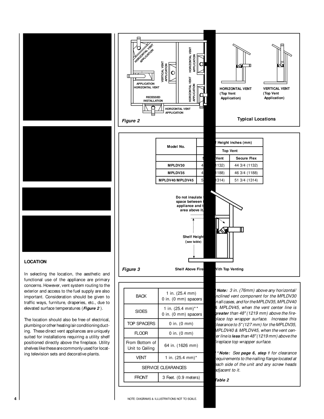
In selecting the location, the aesthetic and functional use of the appliance are primary concerns. However, vent system routing to the exterior and access to the fuel supply are also important. Consideration should be given to traffic ways, furniture, draperies, etc., due to elevated surface temperatures (Figure 2 ).
The location should also be free of electrical, plumbing or other heating/air conditioning duct- ing. These direct vent appliances are uniquely suited for installations requiring a utility shelf positioned directly above the fireplace. Utility shelves like these are commonly used for locat- ing television sets and decorative plants.
Model No. | Shelf Height inches (mm) | ||
|
| ||
Top Vent | |||
| |||
|
|
| |
| Secure Vent | Secure Flex | |
|
|
| |
MPLDV30 | 44 3/4 (1132) | 44 3/4 (1132) | |
|
|
| |
MPLDV35 | 46 3/4 (1188) | 46 3/4 (1188) | |
|
|
| |
MPLDV40/MPLDV45 | 51 3/4 (1314) | 51 3/4 (1314) | |
|
|
| |
Do not insulate the space between the appliance and the area above it.
|
| Shelf Height |
|
|
|
|
|
|
|
|
| ||
|
|
|
|
|
|
|
|
|
|
| |||
|
|
|
|
|
|
|
|
|
|
| |||
|
|
|
|
|
|
|
|
|
|
| |||
|
| (see table) |
|
|
|
|
|
|
|
|
| ||
Figure 3 |
|
|
|
|
|
|
|
|
|
|
| ||
|
|
|
|
|
|
|
|
|
|
|
| ||
|
|
|
|
|
|
|
|
|
|
|
| ||
|
|
|
|
|
|
|
|
|
|
|
| ||
Shelf Above Fireplace With Top Venting | |||||||||||||
|
|
|
|
|
|
|
|
|
|
|
|
|
|
|
|
|
|
|
|
|
|
|
|
|
|
|
|
|
|
|
|
| *Note: 3 in. (76mm) above any horizontal/ | ||||||||
|
| 1 in. (25.4 mm) | |||||||||||
| BACK | inclined vent component for the MPLDV30 | |||||||||||
| 0 in. (0 mm) spacers | ||||||||||||
|
| in all cases, and for the MPLDV35, MPLDV40 | |||||||||||
|
|
|
|
| |||||||||
| SIDES | 1 in. (25.4 mm)** | & MPLDV45, when the vent center line is | ||||||||||
| 0 in. (0 mm) spacers | greater than 48" (1219 mm) above the fire- | |||||||||||
|
| ||||||||||||
|
|
|
|
| place top wrapper surface. Increase this | ||||||||
| TOP SPACERS | 0 in. (0 mm) | |||||||||||
| clearance to 5" (127 mm) for the MPLDV35, | ||||||||||||
|
|
|
|
| MPLDV40 & MPLDV45, when the vent cen- | ||||||||
| FLOOR | 0 in. (0 mm) | |||||||||||
| ter line is less than 48" (1219 mm) above the | ||||||||||||
|
|
|
|
| |||||||||
| From Bottom of | 64 in. (1626 mm) | fireplace top wrapper surface. | ||||||||||
| Unit to Ceiling |
|
|
|
|
|
|
|
|
| |||
|
|
|
| **Note: See page 6, step 1 for clearance | |||||||||
|
|
|
|
| |||||||||
| VENT | 1 in. (25.4 mm)* | |||||||||||
| requirements to the nailing flange located at | ||||||||||||
|
|
|
|
| each side of the unit and any screw heads | ||||||||
| SERVICE CLEARANCES | ||||||||||||
| adjacent to it. | ||||||||||||
|
|
|
|
| |||||||||
| FRONT | 3 Feet. (0.9 meters) | Table 2 | ||||||||||
|
|
|
|
| |||||||||
|
|
|
|
|
|
|
|
|
|
|
|
|
|
| NOTE: DIAGRAMS & ILLUSTRATIONS NOT TO SCALE. |
|
|
|
|
|
|
|
|
| |||
