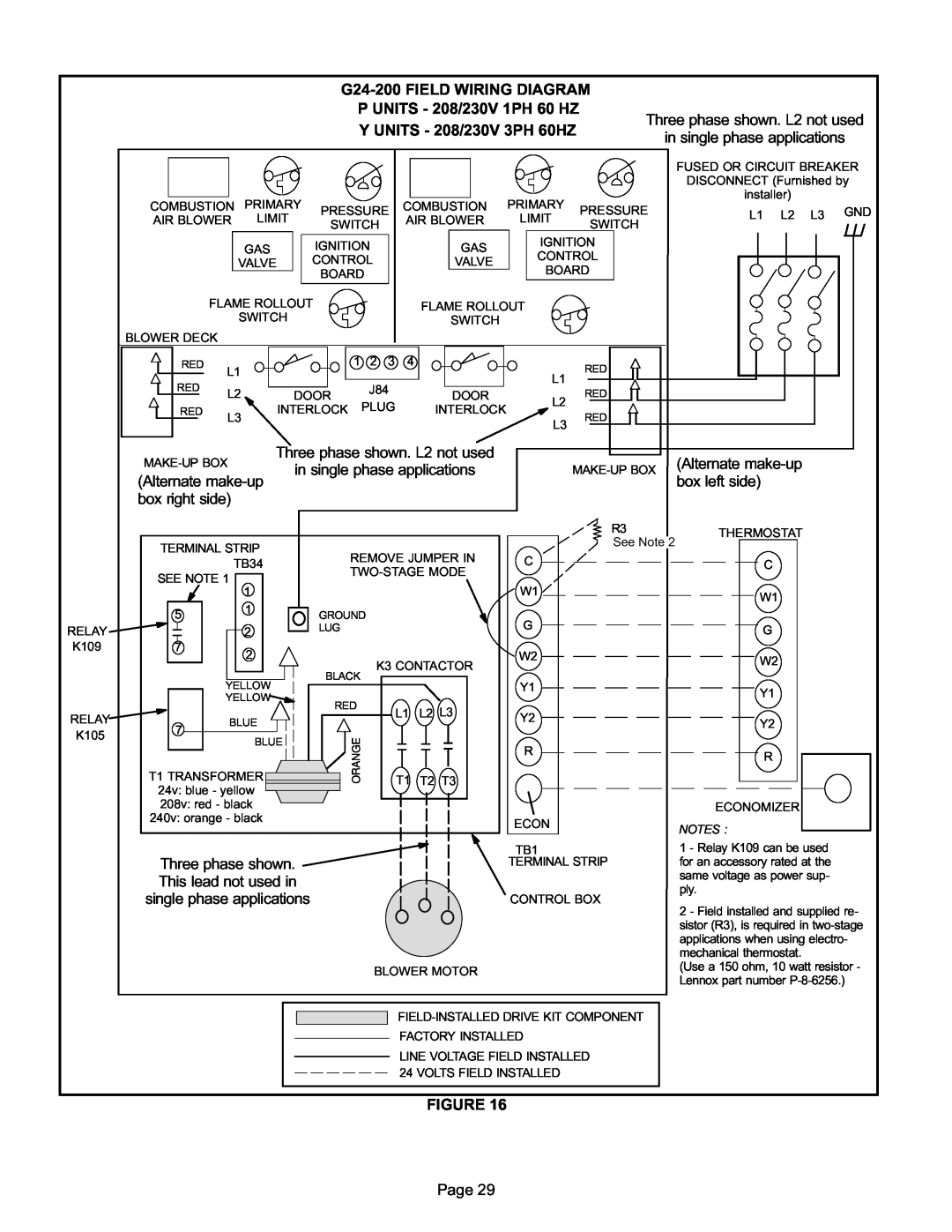
G24-200 FIELD WIRING DIAGRAM
|
| P UNITS − 208/230V 1PH 60 HZ |
| Three phase shown. L2 not used | |||||||
|
| Y UNITS − 208/230V 3PH 60HZ |
| ||||||||
|
|
|
| in single phase applications | |||||||
|
|
|
|
|
|
| |||||
|
|
|
|
|
|
| FUSED OR CIRCUIT BREAKER | ||||
|
|
|
|
|
|
| DISCONNECT (Furnished by | ||||
| PRIMARY |
|
| PRIMARY |
|
| installer) |
|
| ||
COMBUSTION | PRESSURE | COMBUSTION | PRESSURE | L1 | L2 | L3 | GND | ||||
AIR BLOWER | LIMIT | AIR BLOWER | LIMIT | ||||||||
SWITCH | SWITCH |
|
| ||||||||
|
|
|
|
| |||||||
|
|
|
|
|
|
|
|
| |||
| GAS | IGNITION | GAS | IGNITION |
|
|
|
|
| ||
| CONTROL |
|
|
|
|
| |||||
| VALVE | CONTROL | VALVE |
|
|
|
|
| |||
| BOARD |
|
|
|
|
| |||||
|
| BOARD |
|
|
|
|
|
| |||
|
|
|
|
|
|
|
|
|
| ||
FLAME ROLLOUT | FLAME ROLLOUT |
|
|
|
|
|
| ||||
| SWITCH |
|
|
|
|
|
|
| |||
|
| SWITCH |
|
|
|
|
|
|
| ||
|
|
|
|
|
|
|
|
|
| ||
| BLOWER DECK |
|
|
|
|
|
|
|
|
|
|
| RED | L1 |
| 1 | 2 3 4 |
|
|
|
| RED |
|
|
|
|
|
|
|
|
| L1 |
| ||
| RED |
|
|
| J84 |
|
|
|
|
| |
| L2 |
| DOOR |
| DOOR |
|
| RED |
| ||
|
|
| PLUG |
|
| L2 |
| ||||
| RED |
| INTERLOCK |
| INTERLOCK |
|
|
| |||
| L3 |
|
|
| RED |
| |||||
|
|
|
|
|
|
|
| L3 |
| ||
|
|
|
|
|
|
|
|
|
|
| |
| MAKE−UP BOX | Three phase shown. L2 not used |
|
|
| (Alternate make−up | |||||
|
| in single phase applications |
|
| MAKE−UP BOX | ||||||
| (Alternate make−up |
|
|
| box left side) | ||||||
|
|
|
|
|
|
|
|
| |||
| box right side) |
|
|
|
|
|
|
|
|
| |
|
|
|
|
|
|
|
|
|
| R3 | THERMOSTAT |
|
|
|
|
|
|
|
|
|
| See Note 2 | |
| TERMINAL STRIP |
|
|
|
|
|
|
|
| ||
|
| REMOVE JUMPER IN |
|
|
|
| |||||
|
| TB34 |
| C |
|
| C | ||||
|
|
|
|
| |||||||
| SEE NOTE 1 |
|
|
|
|
| |||||
|
|
|
|
|
|
|
|
|
| ||
|
| 1 |
|
|
|
|
| W1 |
|
| W1 |
|
|
|
|
|
|
|
|
|
|
| |
| 5 | 1 |
| GROUND |
|
|
|
|
|
| |
|
|
|
|
| G |
|
|
| |||
RELAY |
| 2 |
| LUG |
|
|
|
|
| G | |
|
|
|
|
|
|
|
|
| |||
K109 | 7 | 2 |
|
|
|
|
| W2 |
|
|
|
|
|
|
| K3 CONTACTOR |
|
| W2 | ||||
|
|
|
|
|
|
|
| ||||
|
|
|
| BLACK |
|
|
|
| |||
|
| YELLOW |
|
|
|
| Y1 |
|
|
| |
|
|
|
|
|
|
|
|
| Y1 | ||
|
| YELLOW |
|
|
|
|
|
|
|
| |
|
|
| RED |
|
|
|
|
|
|
| |
|
|
|
| L1 | L2 | L3 |
|
|
|
| |
RELAY |
| BLUE |
|
| Y2 |
|
| Y2 | |||
7 |
|
|
|
|
|
|
| ||||
|
|
|
|
|
|
|
|
| |||
K105 |
|
| ORANGE |
|
|
|
|
|
|
| |
| BLUE |
|
|
|
|
|
|
| |||
|
|
|
|
| R |
|
|
| |||
| T1 TRANSFORMER |
|
|
|
|
|
| R | |||
|
|
|
|
|
|
|
|
|
| ||
|
|
|
|
|
|
|
|
|
|
| |
| 24v: blue − yellow |
|
| T1 | T2 T3 |
|
|
|
| ||
|
|
|
|
|
|
|
|
|
| ||
| 208v: red − black |
|
|
|
|
|
|
|
| ECONOMIZER | |
| 240v: orange − black |
|
|
|
|
|
|
|
| ||
|
|
|
|
|
| ECON |
|
|
| ||
|
|
|
|
|
|
|
|
|
| NOTES : | |
|
|
|
|
|
|
|
|
|
|
| |
Three phase shown. This lead not used in single phase applications
TB1
TERMINAL STRIP
CONTROL BOX
BLOWER MOTOR
1 − Relay K109 can be used for an accessory rated at the same voltage as power sup- ply.
2 − Field installed and supplied re- sistor (R3), is required in
(Use a 150 ohm, 10 watt resistor − Lennox part number P−8−6256.)
FACTORY INSTALLED
LINE VOLTAGE FIELD INSTALLED 24 VOLTS FIELD INSTALLED
FIGURE 16
Page 29