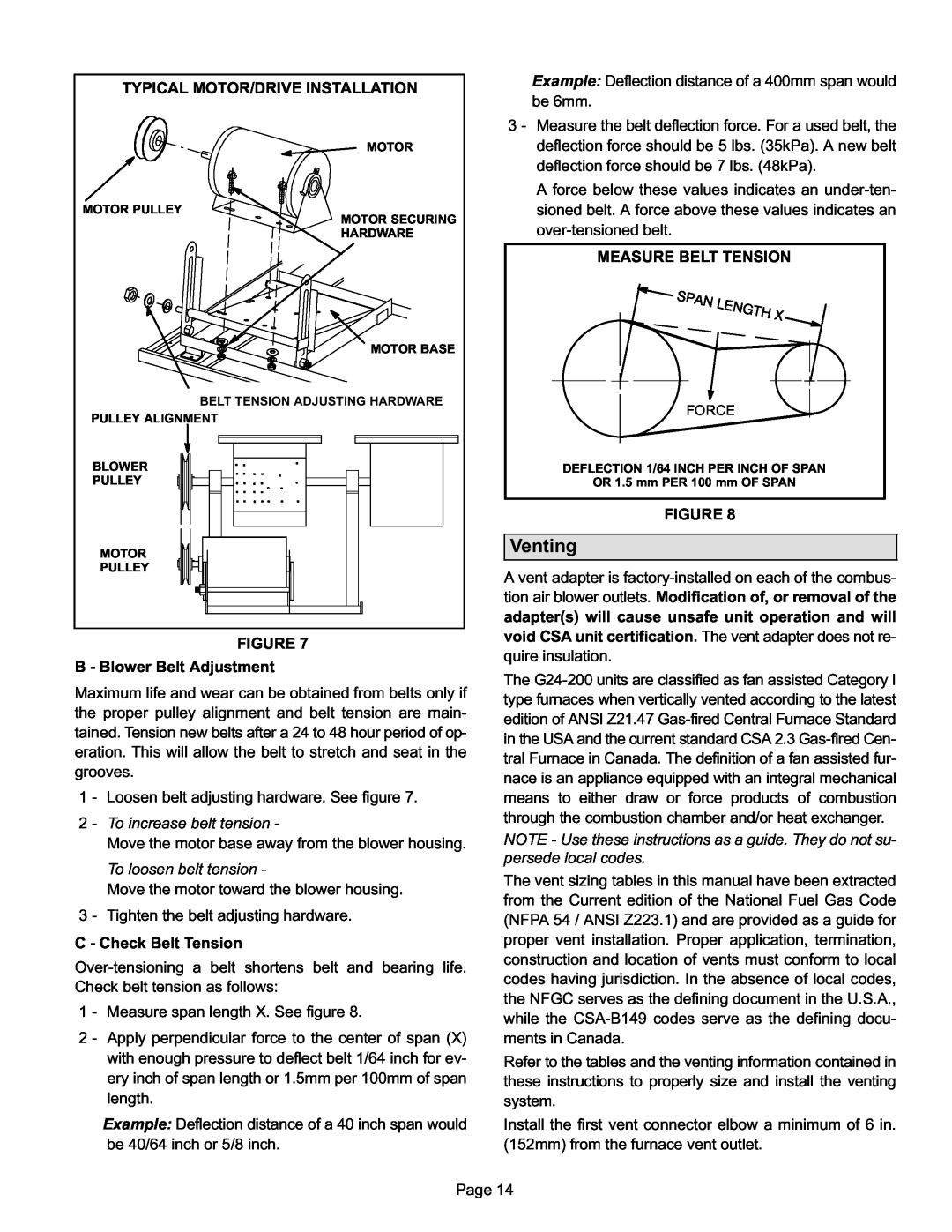
TYPICAL MOTOR/DRIVE INSTALLATION |
MOTOR |
MOTOR PULLEY |
MOTOR SECURING |
HARDWARE |
MOTOR BASE |
BELT TENSION ADJUSTING HARDWARE |
PULLEY ALIGNMENT |
BLOWER |
PULLEY |
MOTOR |
PULLEY |
FIGURE 7
B − Blower Belt Adjustment
Maximum life and wear can be obtained from belts only if the proper pulley alignment and belt tension are main- tained. Tension new belts after a 24 to 48 hour period of op- eration. This will allow the belt to stretch and seat in the grooves.
1 − Loosen belt adjusting hardware. See figure 7.
2 − To increase belt tension −
Move the motor base away from the blower housing.
To loosen belt tension −
Move the motor toward the blower housing. 3 − Tighten the belt adjusting hardware.
C − Check Belt Tension
1 − Measure span length X. See figure 8.
2 − Apply perpendicular force to the center of span (X) with enough pressure to deflect belt 1/64 inch for ev- ery inch of span length or 1.5mm per 100mm of span length.
Example: Deflection distance of a 40 inch span would be 40/64 inch or 5/8 inch.
Example: Deflection distance of a 400mm span would be 6mm.
3 − Measure the belt deflection force. For a used belt, the deflection force should be 5 lbs. (35kPa). A new belt deflection force should be 7 lbs. (48kPa).
A force below these values indicates an
MEASURE BELT TENSION |
FORCE |
DEFLECTION 1/64 INCH PER INCH OF SPAN |
OR 1.5 mm PER 100 mm OF SPAN |
FIGURE 8
Venting
A vent adapter is
The G24−200 units are classified as fan assisted Category I type furnaces when vertically vented according to the latest edition of ANSI Z21.47
NOTE − Use these instructions as a guide. They do not su- persede local codes.
The vent sizing tables in this manual have been extracted from the Current edition of the National Fuel Gas Code (NFPA 54 / ANSI Z223.1) and are provided as a guide for proper vent installation. Proper application, termination, construction and location of vents must conform to local codes having jurisdiction. In the absence of local codes, the NFGC serves as the defining document in the U.S.A., while the CSA−B149 codes serve as the defining docu- ments in Canada.
Refer to the tables and the venting information contained in these instructions to properly size and install the venting system.
Install the first vent connector elbow a minimum of 6 in. (152mm) from the furnace vent outlet.
Page 14