Electrical
![]() CAUTION
CAUTION
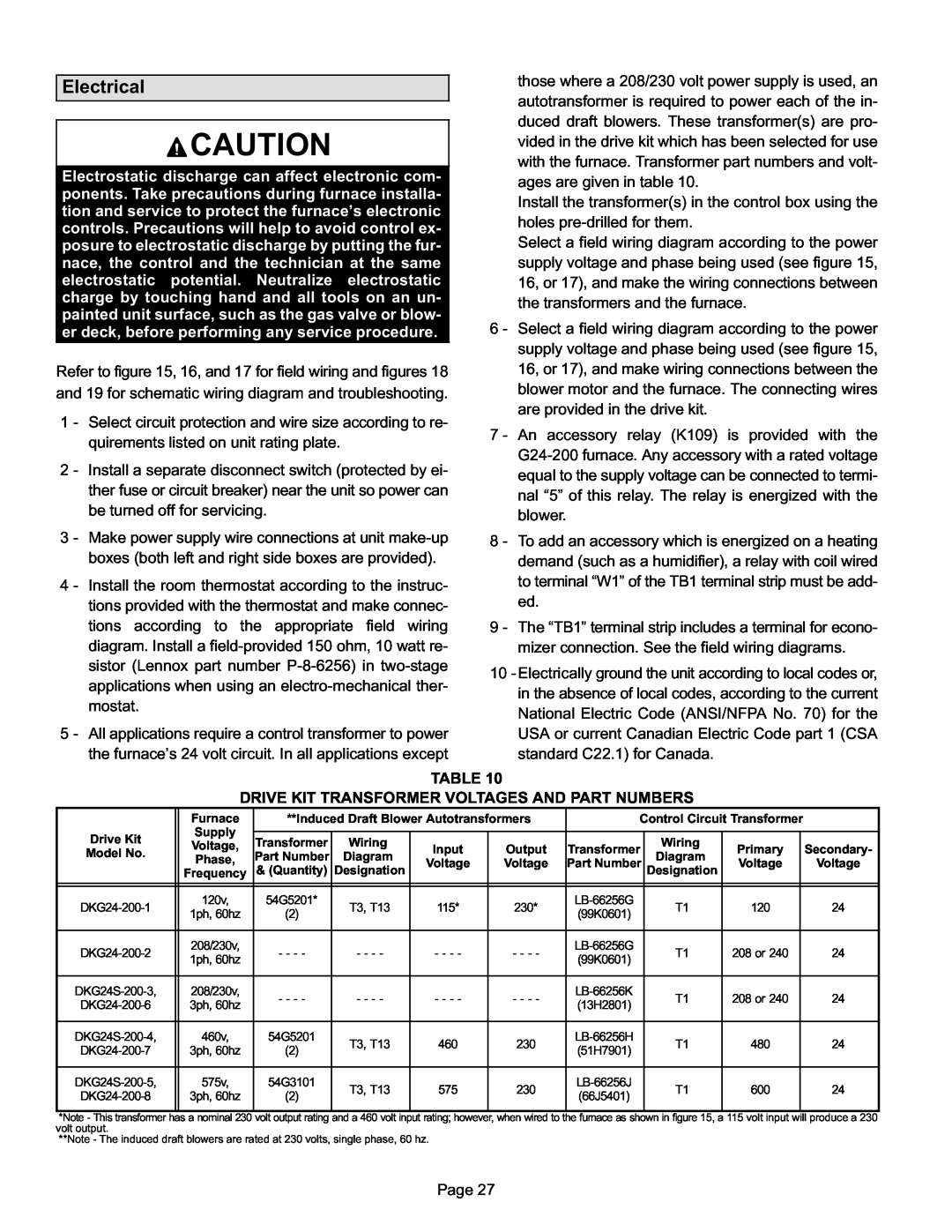
Electrostatic discharge can affect electronic com- ponents. Take precautions during furnace installa- tion and service to protect the furnace’s electronic controls. Precautions will help to avoid control ex- posure to electrostatic discharge by putting the fur- nace, the control and the technician at the same electrostatic potential. Neutralize electrostatic charge by touching hand and all tools on an un- painted unit surface, such as the gas valve or blow- er deck, before performing any service procedure.
Refer to figure 15, 16, and 17 for field wiring and figures 18 and 19 for schematic wiring diagram and troubleshooting.
1 − Select circuit protection and wire size according to re- quirements listed on unit rating plate.
2 − Install a separate disconnect switch (protected by ei- ther fuse or circuit breaker) near the unit so power can be turned off for servicing.
3 − Make power supply wire connections at unit
4 − Install the room thermostat according to the instruc- tions provided with the thermostat and make connec- tions according to the appropriate field wiring diagram. Install a
5 − All applications require a control transformer to power the furnace’s 24 volt circuit. In all applications except
those where a 208/230 volt power supply is used, an autotransformer is required to power each of the in- duced draft blowers. These transformer(s) are pro- vided in the drive kit which has been selected for use with the furnace. Transformer part numbers and volt- ages are given in table 10.
Install the transformer(s) in the control box using the holes
Select a field wiring diagram according to the power supply voltage and phase being used (see figure 15, 16, or 17), and make the wiring connections between the transformers and the furnace.
6 − Select a field wiring diagram according to the power supply voltage and phase being used (see figure 15, 16, or 17), and make wiring connections between the blower motor and the furnace. The connecting wires are provided in the drive kit.
7 − An accessory relay (K109) is provided with the G24−200 furnace. Any accessory with a rated voltage equal to the supply voltage can be connected to termi- nal . The relay is energized with the
blower.
8 − To add an accessory which is energized on a heating demand (such as a humidifier), a relay with coil wired to terminal
ed.
9 − The
mizer connection. See the field wiring diagrams.
10−Electrically ground the unit according to local codes or, in the absence of local codes, according to the current National Electric Code (ANSI/NFPA No. 70) for the USA or current Canadian Electric Code part 1 (CSA standard C22.1) for Canada.
TABLE 10
DRIVE KIT TRANSFORMER VOLTAGES AND PART NUMBERS
| Furnace | **Induced Draft Blower Autotransformers |
| Control Circuit Transformer |
| ||||||
Drive Kit | Supply |
|
|
|
|
|
|
|
|
|
|
Transformer | Wiring |
|
|
|
| Wiring |
|
|
| ||
Voltage, | Input | Output | Transformer | Primary |
| Secondary- | |||||
Model No. |
| ||||||||||
Part Number | Diagram | Diagram |
| ||||||||
Phase, |
| ||||||||||
Voltage | Voltage | Part Number | Voltage |
| Voltage | ||||||
|
| ||||||||||
| & (Quantity) | Designation | Designation |
| |||||||
| Frequency |
| |||||||||
|
|
|
|
|
|
|
|
|
|
|
|
|
|
|
|
|
|
|
|
|
|
|
|
DKG24−200−1 | 120v, | 54G5201* | T3, T13 | 115* | 230* | LB−66256G |
| T1 | 120 |
| 24 |
1ph, 60hz | (2) | (99K0601) |
|
| |||||||
|
|
|
|
|
|
|
|
| |||
|
|
|
|
|
|
|
|
|
|
|
|
DKG24−200−2 | 208/230v, | − − − − | − − − − | − − − − | − − − − | LB−66256G |
| T1 | 208 or 240 |
| 24 |
1ph, 60hz | (99K0601) |
|
| ||||||||
|
|
|
|
|
|
|
|
|
| ||
|
|
|
|
|
|
|
|
|
|
|
|
DKG24S−200−3, | 208/230v, | − − − − | − − − − | − − − − | − − − − | LB−66256K |
| T1 | 208 or 240 |
| 24 |
DKG24−200−6 | 3ph, 60hz | (13H2801) |
|
| |||||||
|
|
|
|
|
|
|
|
| |||
|
|
|
|
|
|
|
|
|
|
|
|
DKG24S−200−4, | 460v, | 54G5201 | T3, T13 | 460 | 230 | LB−66256H |
| T1 | 480 |
| 24 |
DKG24−200−7 | 3ph, 60hz | (2) | (51H7901) |
|
| ||||||
|
|
|
|
|
|
|
| ||||
|
|
|
|
|
|
|
|
|
|
|
|
DKG24S−200−5, | 575v, | 54G3101 | T3, T13 | 575 | 230 | LB−66256J |
| T1 | 600 |
| 24 |
DKG24−200−8 | 3ph, 60hz | (2) | (66J5401) |
|
| ||||||
|
|
|
|
|
|
|
| ||||
|
|
|
|
|
|
|
|
|
|
|
|
*Note − This transformer has a nominal 230 volt output rating and a 460 volt input rating; however, when wired to the furnace as shown in figure 15, a 115 volt input will produce a 230 volt output.
**Note − The induced draft blowers are rated at 230 volts, single phase, 60 hz.
Page 27