Gas Piping
NOTE − The flexible connector supplied with the unit must not be modified and must be installed between the two combination gas controls.
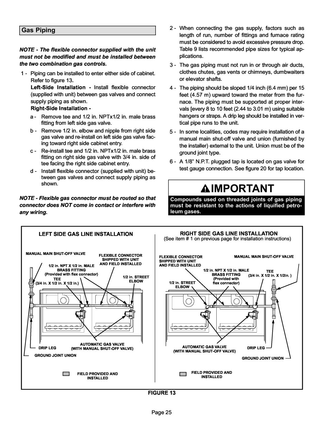
1 − Piping can be installed to enter either side of cabinet. Refer to figure 13.
a − Remove tee and 1/2 in. NPTx1/2 in. male brass fitting from left side gas valve.
b − Remove 1/2 in. elbow and nipple from right side gas valve and
c −
d − Install flexible connector (supplied with unit) be- tween gas valves and connect supply piping as shown.
NOTE − Flexible gas connector must be routed so that connector does NOT come in contact or interfere with any wiring.
2 − When connecting the gas supply, factors such as length of run, number of fittings and furnace rating must be considered to avoid excessive pressure drop. Table 9 lists recommended pipe sizes for typical ap- plications.
3 − The gas piping must not run in or through air ducts, clothes chutes, gas vents or chimneys, dumbwaiters or elevator shafts.
4 − The piping should be sloped 1/4 inch (6.4 mm) per 15 feet (4.57 m) upward toward the meter from the fur- nace. The piping must be supported at proper inter- vals [every 8 to 10 feet (2.44 to 3.01 m) using suitable hangers or straps. A drip leg should be installed in ver- tical pipe runs to the unit.
5 − In some localities, codes may require installation of a manual main
6 − A 1/8" N.P.T. plugged tap is located on gas valve for test gauge connection. See figure 20 for tap location.
![]() IMPORTANT
IMPORTANT
Compounds used on threaded joints of gas piping must be resistant to the actions of liquified petro- leum gases.
LEFT SIDE GAS LINE INSTALLATION
MANUAL MAIN | FLEXIBLE CONNECTOR | ||||
|
|
|
|
| |
|
|
|
|
| SHIPPED WITH UNIT |
|
|
|
| 1/2 in. NPT X 1/2 in. MALE | AND FIELD INSTALLED |
|
|
|
|
| |
|
|
|
| BRASS FITTING |
|
|
|
|
| (Provided with flex connector) | 1/2 in. STREET |
|
|
|
| TEE | |
|
|
|
| ELBOW | |
|
|
|
| ||
|
|
|
| (3/4 in. X 1/2 in. X 1/2 in.) | |
|
|
|
|
| |
| AUTOMATIC GAS VALVE |
DRIP LEG | (WITH MANUAL |
GROUND JOINT UNION
FIELD PROVIDED AND
INSTALLED
RIGHT SIDE GAS LINE INSTALLATION
(See item # 1 on previous page for installation instructions)
FLEXIBLE CONNECTOR |
|
| MANUAL MAIN | ||||||||
SHIPPED WITH UNIT |
|
|
|
|
|
|
|
|
|
|
|
AND FIELD INSTALLED |
|
|
|
|
|
|
|
|
|
|
|
| 1/2 in. NPT X 1/2 in. MALE |
| TEE | ||||||||
|
| BRASS FITTING |
|
|
|
|
| ||||
|
| (3/4 in. X 1/2 in. X 1/2in. ) | |||||||||
|
| (Provided with | |||||||||
|
|
|
|
|
|
|
|
|
| ||
1/2 in. STREET |
| flex connector) |
|
|
|
|
|
|
|
| |
ELBOW |
|
|
|
|
|
|
|
|
|
|
|
|
|
|
|
|
|
|
|
|
|
| |
|
|
|
|
|
|
|
|
|
|
|
|
|
|
|
|
|
|
|
|
|
|
|
|
|
|
|
|
|
|
|
|
|
|
|
|
|
|
|
|
|
|
|
|
|
|
|
|
|
|
|
|
|
|
|
|
|
|
|
|
|
|
|
|
|
|
|
|
|
|
|
|
|
|
|
|
|
|
|
|
|
|
|
|
|
|
|
|
|
|
|
|
|
|
|
|
|
|
|
|
|
|
|
|
|
|
|
|
|
|
|
|
|
|
|
|
|
|
|
|
|
|
|
|
|
|
|
|
|
|
|
|
| AUTOMATIC GAS VALVE | DRIP LEG | ||
(WITH MANUAL | ||||
| ||||
|
|
| GROUND JOINT UNION | |
|
| FIELD PROVIDED AND |
| |
|
|
| ||
|
| INSTALLED |
| |
FIGURE 13
Page 25