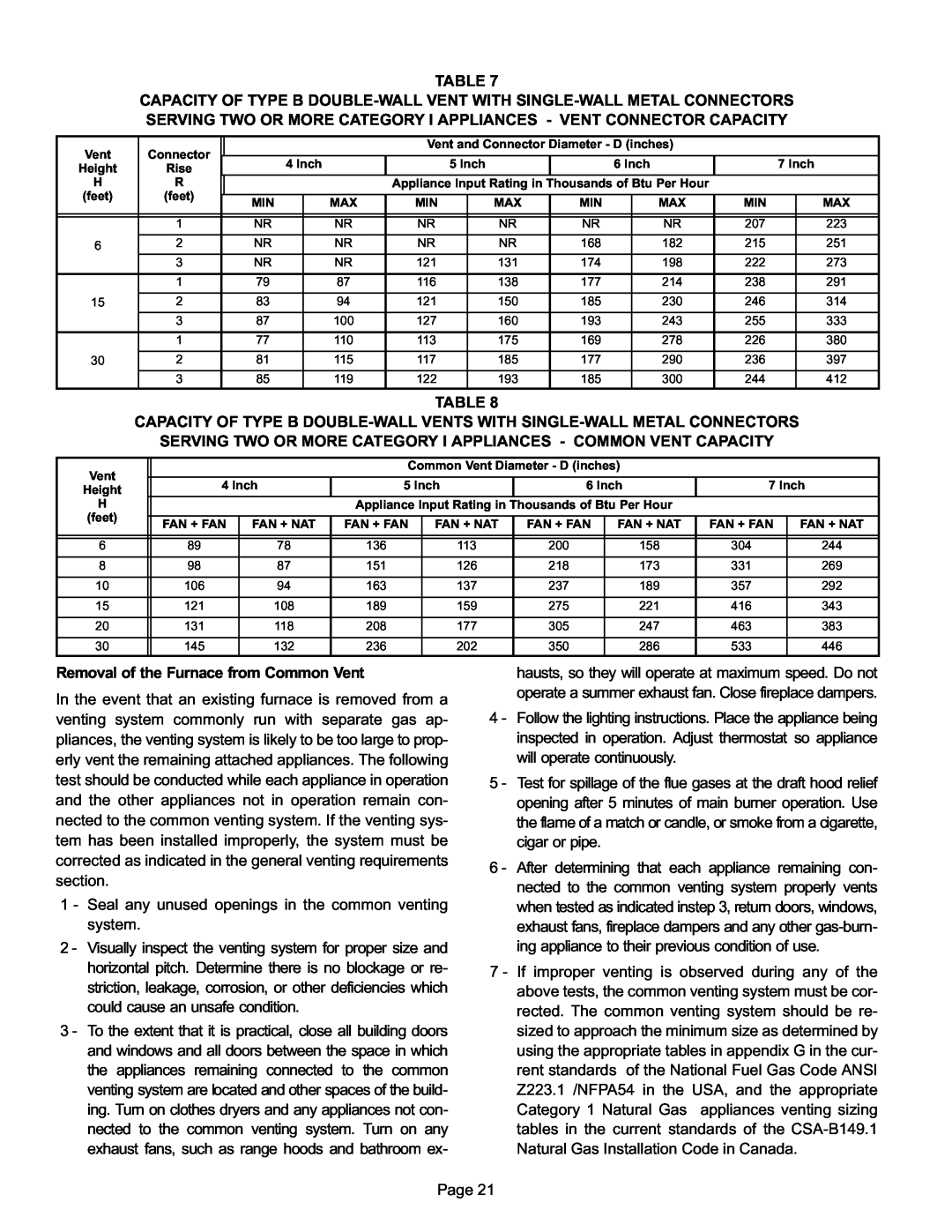
TABLE 7
CAPACITY OF TYPE B
Vent | Connector |
|
|
| Vent and Connector Diameter − D (inches) |
|
|
| |||||
|
|
|
|
|
|
|
|
|
|
|
| ||
Height | Rise |
| 4 Inch |
| 5 Inch |
| 6 Inch |
| 7 Inch | ||||
|
|
|
|
|
|
|
|
|
|
|
| ||
H | R |
|
|
| Appliance Input Rating in Thousands of Btu Per Hour |
|
|
| |||||
(feet) | (feet) |
|
|
|
|
|
|
|
|
|
|
|
|
MIN |
| MAX | MIN |
| MAX | MIN |
| MAX | MIN |
| MAX | ||
|
|
|
|
|
| ||||||||
|
|
|
|
|
|
|
|
|
|
|
|
|
|
|
|
|
|
|
|
|
|
|
|
|
|
|
|
| 1 | NR |
| NR | NR |
| NR | NR |
| NR | 207 |
| 223 |
|
|
|
|
|
|
|
|
|
|
|
|
|
|
6 | 2 | NR |
| NR | NR |
| NR | 168 |
| 182 | 215 |
| 251 |
| 3 | NR |
| NR | 121 |
| 131 | 174 |
| 198 | 222 |
| 273 |
|
|
|
|
|
|
|
|
|
|
|
|
|
|
| 1 | 79 |
| 87 | 116 |
| 138 | 177 |
| 214 | 238 |
| 291 |
|
|
|
|
|
|
|
|
|
|
|
|
|
|
15 | 2 | 83 |
| 94 | 121 |
| 150 | 185 |
| 230 | 246 |
| 314 |
|
|
|
|
|
|
|
|
|
|
|
|
|
|
| 3 | 87 |
| 100 | 127 |
| 160 | 193 |
| 243 | 255 |
| 333 |
|
|
|
|
|
|
|
|
|
|
|
|
|
|
| 1 | 77 |
| 110 | 113 |
| 175 | 169 |
| 278 | 226 |
| 380 |
|
|
|
|
|
|
|
|
|
|
|
|
|
|
30 | 2 | 81 |
| 115 | 117 |
| 185 | 177 |
| 290 | 236 |
| 397 |
|
|
|
|
|
|
|
|
|
|
|
|
|
|
| 3 | 85 |
| 119 | 122 |
| 193 | 185 |
| 300 | 244 |
| 412 |
|
|
|
|
|
|
|
|
|
|
|
|
|
|
TABLE 8
CAPACITY OF TYPE B
SERVING TWO OR MORE CATEGORY I APPLIANCES − COMMON VENT CAPACITY
Vent
Height
H
(feet)
Common Vent Diameter − D (inches)
4 Inch | 5 Inch | 6 Inch | 7 Inch | ||||
|
|
|
|
|
|
|
|
|
| Appliance Input Rating in Thousands of Btu Per Hour |
|
| |||
|
|
|
|
|
|
|
|
FAN + FAN | FAN + NAT | FAN + FAN | FAN + NAT | FAN + FAN | FAN + NAT | FAN + FAN | FAN + NAT |
|
|
|
|
|
|
|
|
|
|
|
|
|
|
|
|
|
6 | 89 | 78 | 136 | 113 | 200 | 158 | 304 | 244 |
|
|
|
|
|
|
|
|
|
8 | 98 | 87 | 151 | 126 | 218 | 173 | 331 | 269 |
|
|
|
|
|
|
|
|
|
10 | 106 | 94 | 163 | 137 | 237 | 189 | 357 | 292 |
|
|
|
|
|
|
|
|
|
15 | 121 | 108 | 189 | 159 | 275 | 221 | 416 | 343 |
|
|
|
|
|
|
|
|
|
20 | 131 | 118 | 208 | 177 | 305 | 247 | 463 | 383 |
|
|
|
|
|
|
|
|
|
30 | 145 | 132 | 236 | 202 | 350 | 286 | 533 | 446 |
|
|
|
|
|
|
|
|
|
Removal of the Furnace from Common Vent
In the event that an existing furnace is removed from a venting system commonly run with separate gas ap- pliances, the venting system is likely to be too large to prop- erly vent the remaining attached appliances. The following test should be conducted while each appliance in operation and the other appliances not in operation remain con- nected to the common venting system. If the venting sys- tem has been installed improperly, the system must be corrected as indicated in the general venting requirements section.
1 − Seal any unused openings in the common venting system.
2 − Visually inspect the venting system for proper size and horizontal pitch. Determine there is no blockage or re- striction, leakage, corrosion, or other deficiencies which could cause an unsafe condition.
3 − To the extent that it is practical, close all building doors and windows and all doors between the space in which the appliances remaining connected to the common venting system are located and other spaces of the build- ing. Turn on clothes dryers and any appliances not con- nected to the common venting system. Turn on any exhaust fans, such as range hoods and bathroom ex-
hausts, so they will operate at maximum speed. Do not operate a summer exhaust fan. Close fireplace dampers.
4 − Follow the lighting instructions. Place the appliance being inspected in operation. Adjust thermostat so appliance will operate continuously.
5 − Test for spillage of the flue gases at the draft hood relief opening after 5 minutes of main burner operation. Use the flame of a match or candle, or smoke from a cigarette, cigar or pipe.
6 − After determining that each appliance remaining con- nected to the common venting system properly vents when tested as indicated instep 3, return doors, windows, exhaust fans, fireplace dampers and any other gas−burn- ing appliance to their previous condition of use.
7 − If improper venting is observed during any of the above tests, the common venting system must be cor- rected. The common venting system should be re- sized to approach the minimum size as determined by using the appropriate tables in appendix G in the cur- rent standards of the National Fuel Gas Code ANSI Z223.1 /NFPA54 in the USA, and the appropriate Category 1 Natural Gas appliances venting sizing tables in the current standards of the CSA−B149.1 Natural Gas Installation Code in Canada.
Page 21