Pin Jumper Settings (see Figure 5)

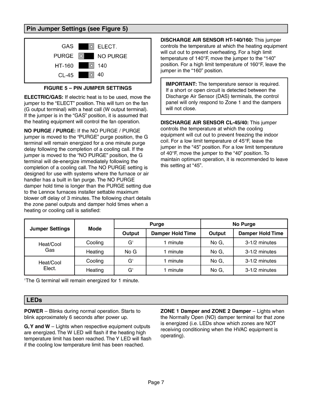
FIGURE 5 – PIN JUMPER SETTINGS

ELECTRIC/GAS: If electric heat is to be used, move the jumper to the “ELECT” position. This will turn on the fan (G output terminal) with a heat call (W output terminal). If the jumper is in the “GAS” position, it is assumed that the heating equipment will control the fan operation.

NO PURGE / PURGE: If the NO PURGE / PURGE jumper is moved to the “PURGE” purge position, the G terminal will remain energized for a one minute purge delay following the completion of a cooling call. If the jumper is moved to the “NO PURGE” position, the G terminal will de-energize immediately following the completion of a cooling call. The NO PURGE setting is designed for use with systems where the furnace or air handler has a built in fan purge. The NO PURGE damper hold time is longer than the PURGE setting due to the Lennox furnaces installer settable maximum blower off delay of 3 minutes. The following chart details the zone panel outputs and damper hold times when a heating or cooling call is satisfied:

DISCHARGE AIR SENSOR HT-140/160: This jumper controls the temperature at which the heating equipment will cut out to prevent overheating. For a high limit temperature of 140°F, move the jumper to the “140” position. For a high limit temperature of 160°F, leave the jumper in the “160” position.

IMPORTANT: The temperature sensor is required. If a short or open circuit is detected between the Discharge Air Sensor (DAS) terminals, the control panel will only respond to Zone 1 and the dampers will not close.

DISCHARGE AIR SENSOR CL-45/40: This jumper controls the temperature at which the cooling equipment will cut out to prevent freezing the indoor coil. For a low limit temperature of 45°F, leave the jumper in the “45” position. For a low limit temperature of 40°F, move the jumper to the “40” position. To maintain optimum operation, it is recommended to leave this setting at “45”.

Jumper Settings

Mode


Purge


No Purge


Output

Damper Hold Time

Output


Damper Hold Time


Heat/Cool

Cooling

G1

1 minute

No G,


3-1/2 minutes


Gas

Heating

No G

1 minute

No G,


3-1/2 minutes


Heat/Cool

Cooling

G1

1 minute

No G,


3-1/2 minutes


Elect.

Heating

G1

1 minute

No G,


3-1/2 minutes


1The G terminal will remain energized for 1 minute.

LEDs

POWER – Blinks during normal operation. Starts to blink approximately 6 seconds after power up.

G, Y and W – Lights when respective equipment outputs are energized. The W LED will flash if the heating high temperature limit has been reached. The Y LED will flash if the cooling low temperature limit has been reached.

ZONE 1 Damper and ZONE 2 Damper – Lights when the Normally Open (NO) damper terminal for that zone is energized (i.e. LEDs show which zones are NOT receiving conditioning when the HVAC equipment is operating).

Page 7

Page 7
Image 7
Lennox International Inc Zone Control Panel, LZP-2 installation instructions Pin Jumper Settings see Figure, LEDs

Zone Control Panel, LZP-2 specifications

Lennox International Inc, a leader in the HVAC industry, has made significant strides in advancing climate control technologies, particularly with their innovative HVAC Zone Control System, designated LZP-2. This system is designed to provide enhanced comfort and energy efficiency in residential and commercial settings by allowing for precise temperature control across different zones within a building.

One of the main features of the LZP-2 HVAC Zone Control System is its ability to operate multiple zones independently. This zoning capability means that different rooms or areas can be set to different temperatures based on usage patterns or individual preferences. Homeowners can enjoy a cooler environment in living spaces while maintaining a warmer temperature in less frequently used zones, such as guest rooms or basements. This tailored approach not only improves comfort but also leads to significant energy savings.

Another key characteristic of the LZP-2 is its smart technology integration. The system can be connected to a comprehensive home automation network, allowing users to manage their HVAC settings remotely. With mobile applications, users can adjust their zone temperatures from anywhere, ensuring optimal comfort when they return home. Integration with smart thermostats also enables the LZP-2 to learn household occupancy patterns, optimizing heating and cooling schedules for maximum efficiency.

The LZP-2 also employs advanced sensor technology to monitor temperature and airflow in various zones. These sensors provide real-time data, enabling the system to make adjustments to maintain desired conditions effectively. This responsiveness not only ensures comfort but also prevents energy waste, leading to reduced utility bills.

In terms of installation and operation, the LZP-2 is designed for user-friendly implementation. Compatible with most HVAC systems, the zoning panel can be integrated seamlessly during the initial setup or retrofitted into existing systems. The modular design allows for expansion, meaning additional zones can be added as needed without significant disruptions.

Lastly, the LZP-2 HVAC Zone Control System is backed by Lennox's longstanding reputation for quality and reliability. With robust build quality and excellent customer support, users can be assured of a dependable solution for their climate control needs.

In summary, the Lennox LZP-2 HVAC Zone Control System represents a significant leap forward in home and commercial climate management, combining advanced zoning capabilities, smart technology, and user-friendly design to create a superior indoor environment with enhanced energy efficiency.