Lennox International Inc LZP-2, Zone Control Panel Application, Features, Installation

Models: Zone Control Panel LZP-2

1 12
Download 12 pages 34.31 Kb
Page 2
Image 2
Application

Application

Two zones

Single-stage electric or gas furnace

Single-stage air conditioner

Multi-stage equipment can be used provided that it stages on it’s own internal controls

Not applicable to heat pump systems

Features

Adjustable high and low discharge air temperature limits

ON/OFF duct air purge control

LED indicators for outputs

Time Delay Override

2 or 3-wire damper compatibility

Installation

The above illustration shows a typical two zone control system.

Install the control panel indoors only.

Do not install the control panel where the tempera- ture will exceed 140°F or will drop below 32°F.

Do not install the control panel on foundation walls, HVAC equipment or duct system where moisture may condense on the enclosure.

Do not install the control panel in a room where it will be exposed to elevated humidity levels such as a laundry room.

1.Remove the cover. Replace the cover when installation is complete.

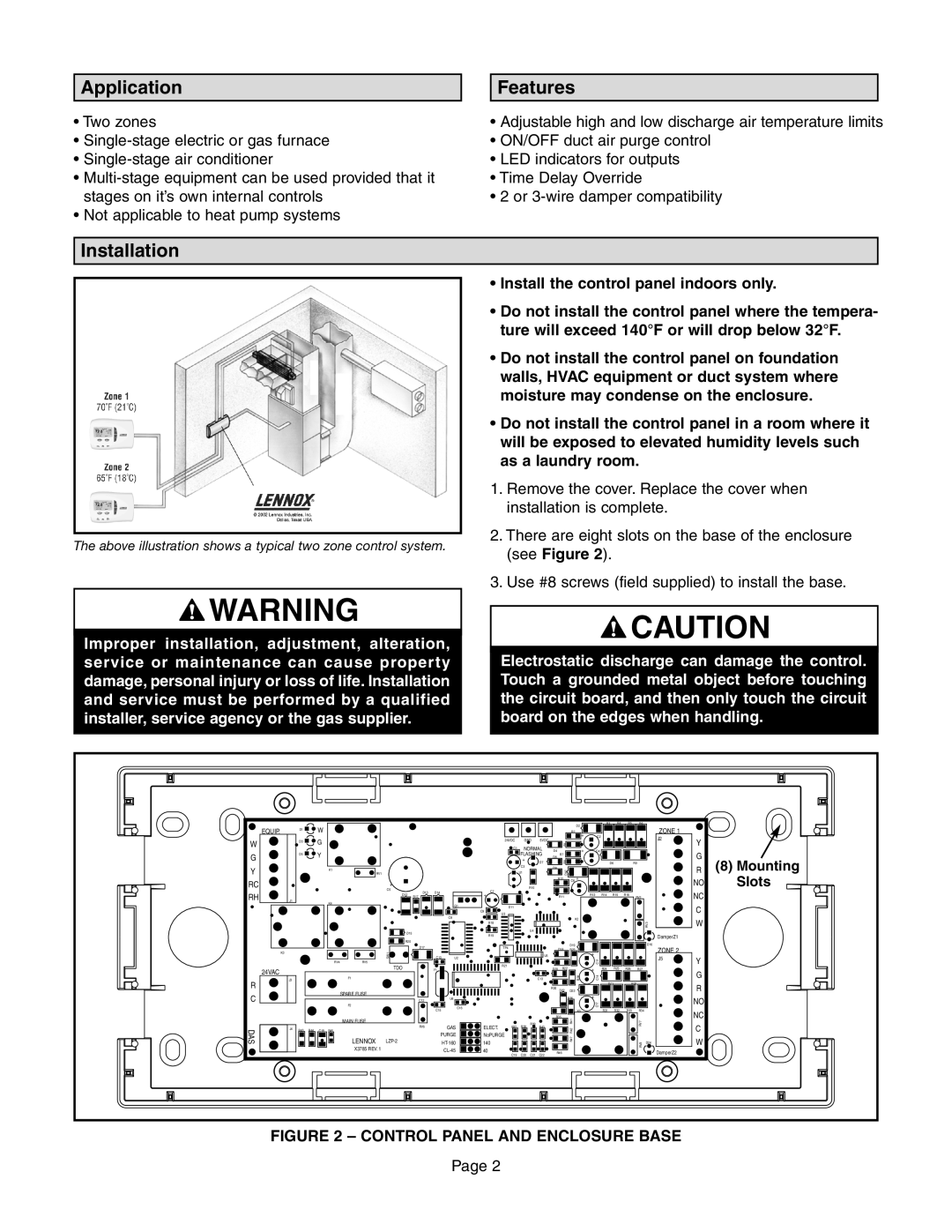
2.There are eight slots on the base of the enclosure (see Figure 2).

3.Use #8 screws (field supplied) to install the base.

FeaturesWARNING

Improper installation, adjustment, alteration, service or maintenance can cause property damage, personal injury or loss of life. Installation and service must be performed by a qualified installer, service agency or the gas supplier.

InstallationCAUTION

Electrostatic discharge can damage the control. Touch a grounded metal object before touching the circuit board, and then only touch the circuit board on the edges when handling.


D2

R3

R4

R5

R6


EQUIP.


D1


W


R2


ZONE 1


+

C2


G


24VDC

GND

5VDC


J2

Y


W


D3


R1


C1

NORMAL

D4


+

C4


G


D5


Y


FLASHING

D8

R7


G


+


D7

R8


D6


R9


(8) Mounting

Y


K1


C3


D9

D10


R


RV1


U1


RC


R12

C6

+


NO

Slots


+


R10


C5

D13

D14


C7


NC


RH


D12


R13

R14

R15

R16


R17


+


R11


RV2


J1


K4


Q1


C


D11


C9

U3


C8


K2


W


R18


RV3


D15


U4


R19


DamperZ1


R20


D16


D17


TP4


D19


ZONE 2


D18

R23


K3


SW1


U5


+C11


C10

U2


J5

Y


RV4

RV5


R21


TDO


D20

R22


+

R24

R25

R26

R27


24VAC


Y1


G


R28

C14


J3


F1


C13


R


D21

R29


R


R30

D22

D23


SPARE FUSE


C


C12


U6


R36

+


NO


C17


F2


C16


C15


K5

R31

R32

R33

R34


NC


MAIN FUSE


R35

R41


RV6


GAS

ELECT.

R37

R38

R39

R40


RV7


C


DAS

J4

R43

R44

C18


R47 R42


R45


LENNOX


PURGE

NoPURGE


W


LZP-2


HT-160

140


RV8

D24


X3785 REV. 1


CL-45

40


R46


DamperZ2


C19

C20

C21

C22


FIGURE 2 – CONTROL PANEL AND ENCLOSURE BASE

Page 2

Page 2
Image 2
Lennox International Inc LZP-2, Zone Control Panel installation instructions Application, Features, Installation