Zone Control Panel, LZP-2 specifications
Lennox International Inc, a leader in the HVAC industry, has made significant strides in advancing climate control technologies, particularly with their innovative HVAC Zone Control System, designated LZP-2. This system is designed to provide enhanced comfort and energy efficiency in residential and commercial settings by allowing for precise temperature control across different zones within a building.One of the main features of the LZP-2 HVAC Zone Control System is its ability to operate multiple zones independently. This zoning capability means that different rooms or areas can be set to different temperatures based on usage patterns or individual preferences. Homeowners can enjoy a cooler environment in living spaces while maintaining a warmer temperature in less frequently used zones, such as guest rooms or basements. This tailored approach not only improves comfort but also leads to significant energy savings.
Another key characteristic of the LZP-2 is its smart technology integration. The system can be connected to a comprehensive home automation network, allowing users to manage their HVAC settings remotely. With mobile applications, users can adjust their zone temperatures from anywhere, ensuring optimal comfort when they return home. Integration with smart thermostats also enables the LZP-2 to learn household occupancy patterns, optimizing heating and cooling schedules for maximum efficiency.
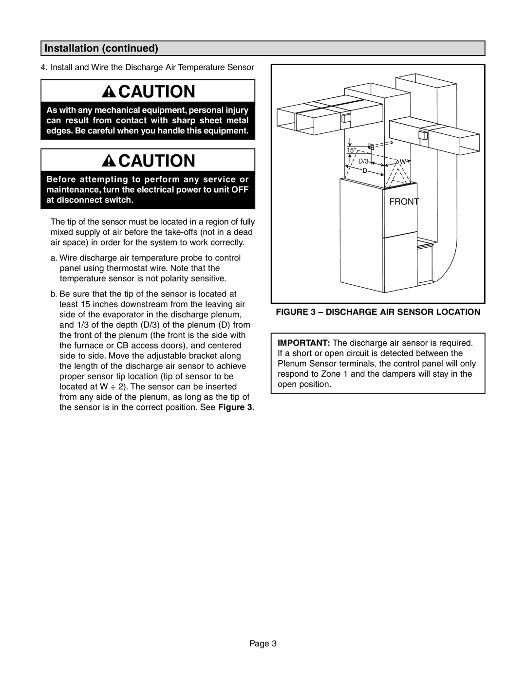
The LZP-2 also employs advanced sensor technology to monitor temperature and airflow in various zones. These sensors provide real-time data, enabling the system to make adjustments to maintain desired conditions effectively. This responsiveness not only ensures comfort but also prevents energy waste, leading to reduced utility bills.
In terms of installation and operation, the LZP-2 is designed for user-friendly implementation. Compatible with most HVAC systems, the zoning panel can be integrated seamlessly during the initial setup or retrofitted into existing systems. The modular design allows for expansion, meaning additional zones can be added as needed without significant disruptions.
Lastly, the LZP-2 HVAC Zone Control System is backed by Lennox's longstanding reputation for quality and reliability. With robust build quality and excellent customer support, users can be assured of a dependable solution for their climate control needs.
In summary, the Lennox LZP-2 HVAC Zone Control System represents a significant leap forward in home and commercial climate management, combining advanced zoning capabilities, smart technology, and user-friendly design to create a superior indoor environment with enhanced energy efficiency.

