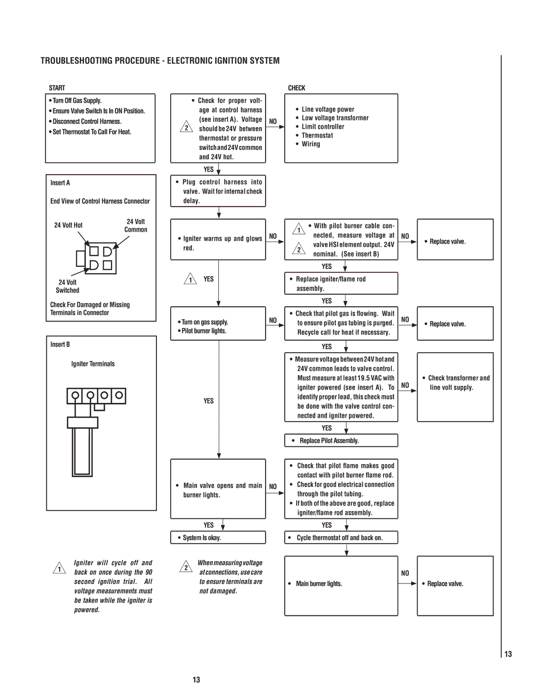
MPB35ST-NM specifications
Lennox International Inc., a leader in the heating, ventilation, and air conditioning (HVAC) industry, offers the MPB35ST-NM model as part of its comprehensive range of integrated solutions. This finely engineered unit is designed to provide exceptional performance and energy efficiency while ensuring optimum home comfort.One of the standout features of the Lennox MPB35ST-NM is its modular design, which allows for flexible installation and easy integration with existing systems. This unit is particularly beneficial for residential settings where space may be at a premium. It also supports efficient zoning, enabling tailored climate control for different areas of the home.
The MPB35ST-NM utilizes advanced multi-stage heating technology, which means it can adjust its output to match the specific demands of the environment. This significantly enhances energy efficiency and reduces operational costs. The unit operates with a high Seasonal Energy Efficiency Ratio (SEER) rating, ensuring optimal performance without excessive energy consumption.
Additionally, the MPB35ST-NM is equipped with smart technology features that allow homeowners to monitor and manage their heating system remotely. Through a user-friendly app, users can adjust settings, schedule maintenance reminders, and receive performance alerts, all of which contribute to an improved user experience.
Another key characteristic of the MPB35ST-NM is its quiet operation. The unit is designed with sound-dampening components that minimize noise during operation, ensuring that homeowners can enjoy a peaceful living environment.
Durability is another hallmark of Lennox products, and the MPB35ST-NM is no exception. Constructed with high-quality materials, this unit is built to withstand the rigors of daily use while offering long-lasting reliability. Additionally, Lennox provides robust customer support and warranty options, giving customers peace of mind in their investment.
In summary, the Lennox International Inc. MPB35ST-NM model stands out as a leader in home heating solutions. With its adaptable design, energy-efficient technology, smart features, quiet operation, and dependable durability, it meets the evolving needs of modern households, making it an excellent choice for those seeking comfort and efficiency in their heating systems.

