Cleaning Logs And Burner
Carefully remove the logs (use care when han- dling the fiber logs, as they become quite fragile after curing). Vacuum out any foreign matter (lint, carbon, etc.) on the burner. Ensure the burner ports are “open.” Remove any carbon deposits from the under side of the logs using
avacuum cleaner, or a soft bristled brush (i.e. paint brush). Note: Improper positioning of logs can create carbon build-up and will alter the performance of the appliance.
Replacing Logs -
If the logs become damaged by accident or improper handling and need replacement, use only the proper replacement logs from manufac- turer (see Page 23 for ordering information).
Re-Install Embers, Logs and Vermiculite
-Carefully follow placement instructions on Pages 9 to 12 ). All logs should fit onto cor- responding pins and/or log stoppers. This will ensure a proper flame and safe combustion.
Inspect Wiring
Refer to wiring diagrams on Page 14.
 WARNING
Label all wires prior to discon- nection when servicing con- trols. Wiring errors can cause improper and dangerous opera- tion. Verify proper operation after servicing.
Inspect and clean all wire connections. Ensure that there is no melting or damage. Inspection should include:
•Terminals at the Valve
•OFF/ON Switch
•(Optional Control Switch) Remote Control or Remote Wall Switch Kit
Inspect Burner Flame Appearance
Ensure that the burner flame appearance resembles the flame shown in Figure 15 and as described in Flame Appearance and Sooting on Page 13. The Homeowner must contact a qualified service technician at once if any abnormal condition is observed.
Small Area Paint Touch-up
The finish of the appliance is a high qual- ity powdercoat. Only use factory supplied powdercoat paint kit for touch-ups. Paint is available at your local authorized Lennox Hearth Products dealer (cat. no. 90L74). Never attempt to paint a hot fireplace.
Do not attempt to repaint the appliance until the finish is completely cured (see Burn-In Period on Page 3 ). If the surface later becomes stained or marred, it may be lightly sanded and touched up with spray paint.
Front Glass Enclosure Panel
 WARNING
Do not attempt to touch the front enclosure glass with your hands while the fireplace is in use.
 WARNING
Do not operate appliance with the glass front removed, cracked or broken. Replacementoftheglass should be done by a licensed or qualified service technician.
 WARNING
Handle this glass with extreme care! Tempered glass is suscep- tible to damage – do not scratch or handle roughly while rein- stalling the glass door frame.
 WARNING
Do not attempt to substitute the materials used on this door, or replace cracked or broken glass with any materials other than those provided by the appliance manufacturer.
 WARNING
The glass door of this appli- ance must only be replaced as a complete unit as provided by the manufacturer. Do not attempt to replacebroken,crackedorchipped glass separately.
These fireplaces are designed to operate only with the glass enclosure panels properly installed. Generally the glass enclosure panels should not be removed except to gain access to the components within the firebox, and the appliance may only be operated without the front glass enclosure panel in place for very brief periods of time during initial appliance checkout and adjustment.
During this appliance checkout and adjust- ment period, a potential safety hazard exists
-EXERCISE EXTREME CAUTION to prevent the occurrence of any burn injuries from the exposed flames or hot surfaces. Also note, that while the front glass enclosure panel (or any of the panels) is removed, the flame appearance will appear to be smaller than normal.
NOTE: DIAGRAMS & ILLUSTRATIONS NOT TO SCALE.
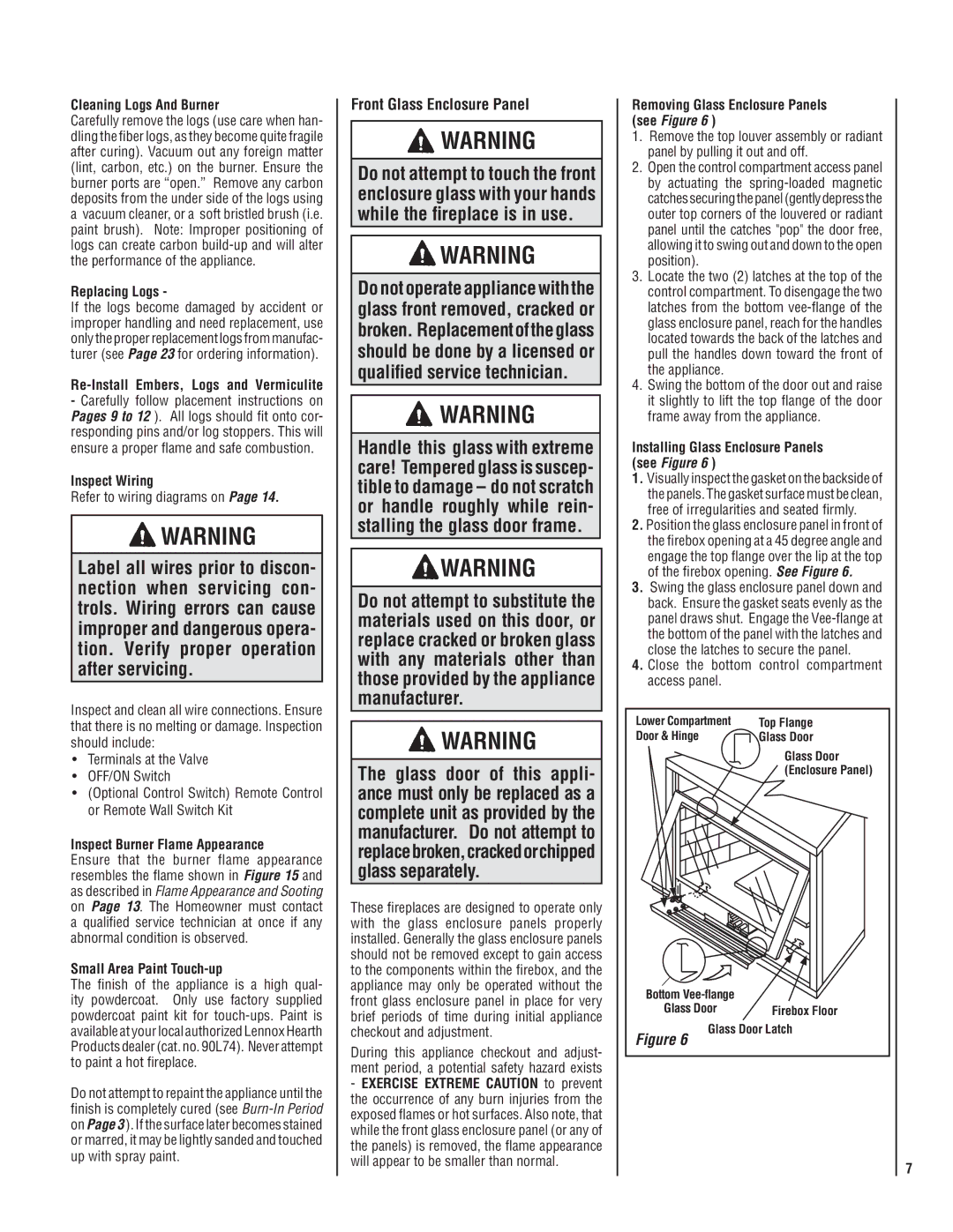
Removing Glass Enclosure Panels
(see Figure 6 )
1.Remove the top louver assembly or radiant panel by pulling it out and off.
2.Open the control compartment access panel by actuating the spring-loaded magnetic catches securing the panel (gently depress the outer top corners of the louvered or radiant panel until the catches "pop" the door free, allowing it to swing out and down to the open position).
3.Locate the two (2) latches at the top of the control compartment. To disengage the two latches from the bottom vee-flange of the glass enclosure panel, reach for the handles located towards the back of the latches and pull the handles down toward the front of the appliance.
4.Swing the bottom of the door out and raise it slightly to lift the top flange of the door frame away from the appliance.
Installing Glass Enclosure Panels
(see Figure 6 )
1.Visually inspect the gasket on the backside of the panels. The gasket surface must be clean, free of irregularities and seated firmly.
2.Position the glass enclosure panel in front of the firebox opening at a 45 degree angle and engage the top flange over the lip at the top of the firebox opening. See Figure 6.
3.Swing the glass enclosure panel down and back. Ensure the gasket seats evenly as the panel draws shut. Engage the Vee-flange at the bottom of the panel with the latches and close the latches to secure the panel.
4.Close the bottom control compartment access panel.
Lower Compartment | Top Flange |
Door & Hinge | Glass Door |
| Glass Door |
| (Enclosure Panel) |
Bottom Vee-flange | |
Glass Door | Firebox Floor |
Glass Door Latch |
Figure 6 | |
7