Millivolt appliances are fitted with an OFF/ON Rocker Switch located behind the control compartment access panel, below the appli- ance front glass enclosure panel (see Figure 1 for location). Once the pilot is lit, the OFF/ON rocker switch will control the appliance OFF/ON burner operation. To operate: Toggle the switch between its ON and OFF positions.
If your millivolt appliance is equipped with an optional remote switch kit (wall switch or remote control) and the pilot is lit, the appliance main burner may be turned on and off using the optional switch. When using an optional remote switch, turn off the standard OFF/ON switch.
Note: To prevent excessive resistance in burner circuit (which can cause burner operation prob- lems), only one burner control switch should be wired to valve. Therefore, if an optional control switch is installed, the standard Off/On switch and wires should be removed.
Electronic Appliances -
To light electronic appliances refer to the detailed lighting instructions found on Pagex
19.Electronic appliance lighting instructions mayalsobefoundonthepulloutlightinginstruc- tion labels attached to the gas control valve.
Once the pilot is lit, if your electronic appliance is equipped with an optional burner control switch kit the appliance main burner may be turned on and off using the optional switch (See Optional Accessories on Pagex 15 - wall switch, or remote control Receiver).
Honeywell Electronic Gas Valve
Manifold
Pressure ON / OFF Switch
Port
| | | Inlet |
C | | | Pressure |
ONTROL | OFF ON | N | Port |
| | I | |
IGNITER | | | |
| | IPS | |
| Figure 3 | Electronic Gas |
| Control Valve |
| |
Variable Flame Height Adjustment ( Millivolt Appliances only)
1. All Millivolt appliances are equipped with a variable gas control valve. Flame height for these models may be adjusted through a range between fixed low and high settings while the appliance is in operation. Adjust the flame height as desired after lighting the appliance by rotating the variable adjustment control knob (HI/LO) located on the front of the valve (refer to Figure 2 ).
2.During the first initial burns of these appli- ances, there will be some odor emitted (see Burn-In Period on Page 3 ).
3.Keep the lower control compartment clean by vacuuming or brushing at least twice a year. More frequent cleaning may be required due to excessive lint from carpeting, bedding materials, pet hair, etc. It is very important that the control compartments, burners and circulating air passageways of the appliance are kept clean.
4.Always turn off gas to the pilot (millivolt appliances) and let the appliance cool down before cleaning. Before re-lighting, refer to the lighting instructions in this manual. Lighting instructions may also be found on the pull out lighting instruction labels attached to the gas control valve.
5.Always keep the appliance area clear and free from combustible materials, gasoline and other flammable liquids.
6.Remember, Millivolt appliances have a con- tinuous burning pilot flame. Exercise cau- tion when using products with combustible vapors.
VENT OPERATION TEST
A vent operation test is required as part of the installation to verify that proper venting condi- tions exist and should be done periodically to ensure nothing has changed that would affect proper venting of the appliance.
Procedure:
1.ENSURE APPLIANCE IS OFF (PILOT ONLY) AND COOL.
2.Open both latches on one of the glass enclosure doors and slightly prop it open at the bottom (approx. 1/4” gap). See Figure 6 on Page 9.
3.Turn on all the exhaust fans in the dwelling (and any other appliances which remove air from the dwelling, such as a furnace or clothes dryer, etc.).
4.Ensure that all the doors and windows in the room where the fireplace is located are closed.
5.Light the appliance (see Lighting Instruc- tions, Pages 18 & 19 ). Adjust flame height to highest setting and operate for approximately 5-10 minutes. Do not leave appliance unattended.
6.Take a smoke producing device and move it alongthebottomedgeoftheglassdoor(where it is cracked open). If smoke is drawn into the firebox, the vent operation is adequate.
IF THE SMOKE IS NOT DRAWN INTO THE FIREBOX, TURN THE APPLIANCE OFF AND CALL A QUALIFIED SERVICE TECHNICIAN.
NOTE: DIAGRAMS & ILLUSTRATIONS NOT TO SCALE.
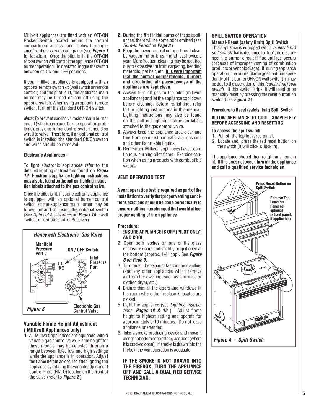
SPILL SWITCH OPERATION
Manual-Reset (safety limit) Spill Switch This appliance is equipped with a (safety limit) spill switch that is designed to "trip" and discon- nect the burner circuit if flue spillage occurs (because of improper venting of combustion products or vent blockage). If, during appliance operation, the burner flame goes out (indepen- dently of the burner OFF/ON wall switch), it may be due to the operation of this (safety limit) spill switch. If this switch "trips" it will need to be manually reset by pressing the reset button on switch (see Figure 4 ).
Procedure to Reset (safety limit) Spill Switch
ALLOW APPLIANCE TO COOL COMPLETELY BEFORE ACCESSING AND RESETTING
To access the spill switch:
1.Pull off the top louvered panel.
2.Locate and press the red reset button on the switch (it will click & lock in).
The appliance should then relight and remain lit. If this does not occur, turn off the appliance and call a qualified service technician.
| | Press Reset Button on |
| | Spill Switch |
| | Remove Top |
| | Louvered |
| | Panel (or |
| | optional |
| | radiant panel, |
| | if applicable) |
Figure 4 | - | Spill Switch |
5