ThinkServer User Guide
Fourth Edition March Copyright Lenovo 2010
Appendix C Notices on
Contents
Appendix A. RAID battery card Assembly 105
Iii
Safety information
제품을 사용하기 전에 제품과 함께 제공되는 문서 DVD의 다국어 안전 지침을 주의 깊게 읽어보십시오
在使用本产品之前,请务必先阅读和了解产品附带的文档 DVD 中的多语言安全说明。
Statement
≥ 18 kg 39.7 lb ≥ 32 kg 70.5 lb ≥ 55 kg 121.2 lb
Vii
Statement Following label indicates a potential heat hazard
Copyright Lenovo 2010
ThinkServer User Guide
Server documentation
General information
Introduction
Documentation DVD
Printed documents
Remote Management User Guide
Document only for trained service personnel
ThinkServer User Guide
Task Where to find the information
Server setup road map
ThinkServer User Guide
What is included with your server
Features and technologies
Features
Specifications
Hard disk drive expansion bays
Microprocessors Supports up to Optical drive Environment
Depending on the model
Expansion slots
Software programs
Reliability, availability, and serviceability
EasyStartup
EasyManage
ThinkServer User Guide
Rear view
Locating parts, controls, LEDs, and connectors
Front view
Front control panel
Connector Description
Hard disk drive status Description
State Color Description
Ethernet LEDs
Server component locations
Locating server components
Locating major parts on the system board
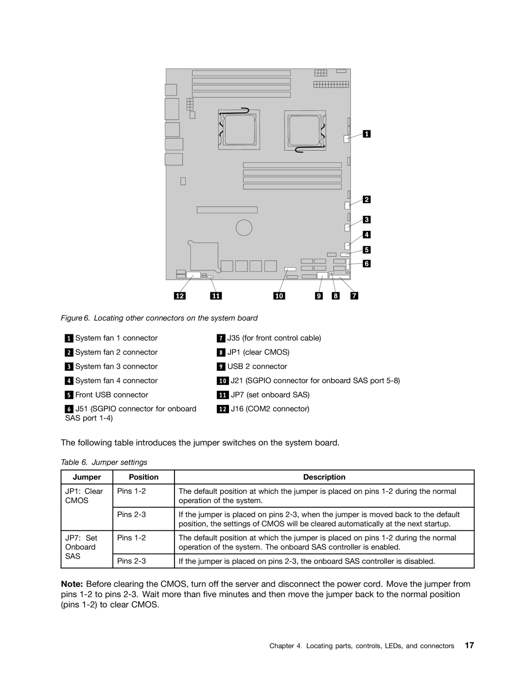
Locating parts on the system board
Cmos
Jumper Position Description
Backplane connector locations
Locating connectors on the backplane
Basic guidelines
Installing, removing, or replacing hardware
Guidelines
Handling static-sensitive devices
System reliability guidelines
Removing the server cover
Working inside the server with the power on
Installing or removing a memory module
Installing, removing, or replacing optional hardware devices
Installing a memory module
Memory module installation rules
Dimm slot One Dimm Two DIMMs Three DIMMs Four DIMMs
Dimm slot Two DIMMs Four DIMMs Six DIMMs Eight DIMMs
Opening the retaining clips of the memory slot
What to do next
Removing a memory module
Removing or installing internal drives
Removing the optical drive
Removing the drive access panel
Slide out the optical drive cage with the optical drive
Installing the optical drive
Installing, removing, or replacing hardware
Removing the drive access panel
Slide out the optical drive cage
Remove the bezel of the optical drive cage
Slide the cage with the optical drive into place
Removing a hot-swap hard disk drive
Installing the optical drive cage retaining screw
Removing the hard disk drive tray assembly
Installing a hot-swap hard disk drive
Removing the riser card assembly
Removing or installing the riser card assembly
Removing the riser card assembly
Installing the riser card assembly
Installing the riser card assembly
Installing or removing a PCI card
PCI card slots on the riser card assembly
Installing a PCI card
Removing a PCI card
Removing the system board battery
Installing, removing, or replacing hardware devices
Removing or installing the system board battery
Removing the system board battery
Installing the system board battery
Removing the RAID controller
Removing or installing the RAID controller
Removing the RAID controller
Installing the ThinkServer 8708ELP SAS RAID Adapter
Installing, removing, or replacing hardware
Top view of the battery card assembly
Installing the battery card assembly
Connecting the mini SAS signal cables
Installing the ThinkServer 8708EM2 RAID Adapter
Top view of the battery card assembly
Connecting the mini SAS signal cables to the RAID controller
What to do next
Installing the ThinkServer RAID 700 Adapter
J6B1 BBU connector
Connecting the mini SAS signal cables to the RAID controller
Removing the Ethernet card
Removing or installing the Ethernet card
Installing the Ethernet card
Removing the microprocessor fan duct
Removing or installing the microprocessor fan duct
Installing the microprocessor fan duct
Removing the power supply
Removing or installing the power supply
Removing the power supply
Installing the power supply
Removing the bay bezel for the power supply
Removing the system fans
Removing or installing the system fans
Removing the system fans
Installing the system fans
Removing the heat sink
Removing or installing the heat sink
Removing the heat sink
Installing the heat sink
Removing the microprocessor
Removing or installing the microprocessor
Removing the microprocessor
Installing the microprocessor
Lifting the handle
Removing the microprocessor socket cover
Connecting the cables
Completing the parts replacement
Installing the server cover
Turning off the server
Updating the server configuration
Turning on the server
Connecting external devices
ThinkServer User Guide
Using the Setup Utility program
Configuring the server
Introduction of the Bios items
Starting the Setup Utility program
Submenus under the Hardware Health Configuration
Configuration on
Submenus under the Remote Access Configuration
Option Description
Option Description
Submenus under the SuperIO Configuration
Sub-item Option Description
Option Description Items and options with BMC configuration
Items and options without BMC configuration
Submenu under the Intel VT-d Configuration
Items under the Boot menu
Exiting the Setup Utility program
Using passwords
Password considerations
Change Supervisor Password Change User Password
RAID controllers
Setting, changing, or deleting a password
Before you use the EasyStartup DVD
Using the ThinkServer EasyStartup program
Setup and configuration
Typical operating system installation
Configuring RAID
SAS connectors and J51 connector on the system board
Connecting mini-SAS cable
Starting the Configuration Utility program
Accessing the Adapter Properties window
Creating the RAID 1 array
SAS RAID settings
Creating or deleting the RAID 1 array
Deleting the RAID 1 array
Accessing the SAS Topology window
Configuring the Gigabit Ethernet controller
Updating the firmware
Using the EasyUpdate Firmware Updater program
Installing the ThinkServer EasyManage program
Troubleshooting tables
Troubleshooting
DVD drive problems
Symptom Action
Intermittent problems
General problems
Hard disk drive problems
Memory problems
Keyboard, mouse, or pointing-device problems
Microprocessor problems
Monitor problems
Optional-device problems
Power problems
Serial port problems
Solving power problems
Software problems
Universal Serial Bus USB port problems
Solving undetermined problems
Solving Ethernet controller problems
Event logs
Viewing event logs without restarting the server
Diagnostic LEDs on the front control panel
System event log
Onboard debug digitron
Battery life and data retention time
Appendix A. RAID battery card assembly
Battery technology LiON
105
BBU name Data retention time
Using the documentation
Appendix B. Getting information, help, and service
Information resources
ThinkServer Web site
Before you call
Help and service
Calling for service
Purchasing additional services
Using other services
ThinkServer User Guide
111
Appendix C. Notices
Important notes
Trademarks
Battery return program
Requirement for batteries containing perchlorate
Contaminant Limits
Particulate contamination
Important information for the European Directive 2002/96/EC
ThinkServer User Guide
Appendix C. Notices
ThinkServer User Guide
China RoHS
Restriction of Hazardous Substances Directive RoHS
German Ordinance for Work gloss statement
Turkish statement of compliance
Electronic emission notices
Federal Communications Commission FCC Statement
Appendix C. Notices
ThinkServer User Guide
123
Index
General problems German gloss statement Getting help
125
USB