•“1030 Bottom slot cover” on page 46
•“1040 Memory modules” on page 46
•“1050 Hard disk drive assembly” on page 47
•“1060 PCI Express Mini Card for wireless LAN” on page 49
•“1070 Thermal fan assembly” on page 51
•“1080 Microprocessor” on page 53
•“1090 Keyboard” on page 54
•“1100 Keyboard bezel” on page 57
•“1120 Backup battery” on page 60
•“1130 System board assembly” on page 61
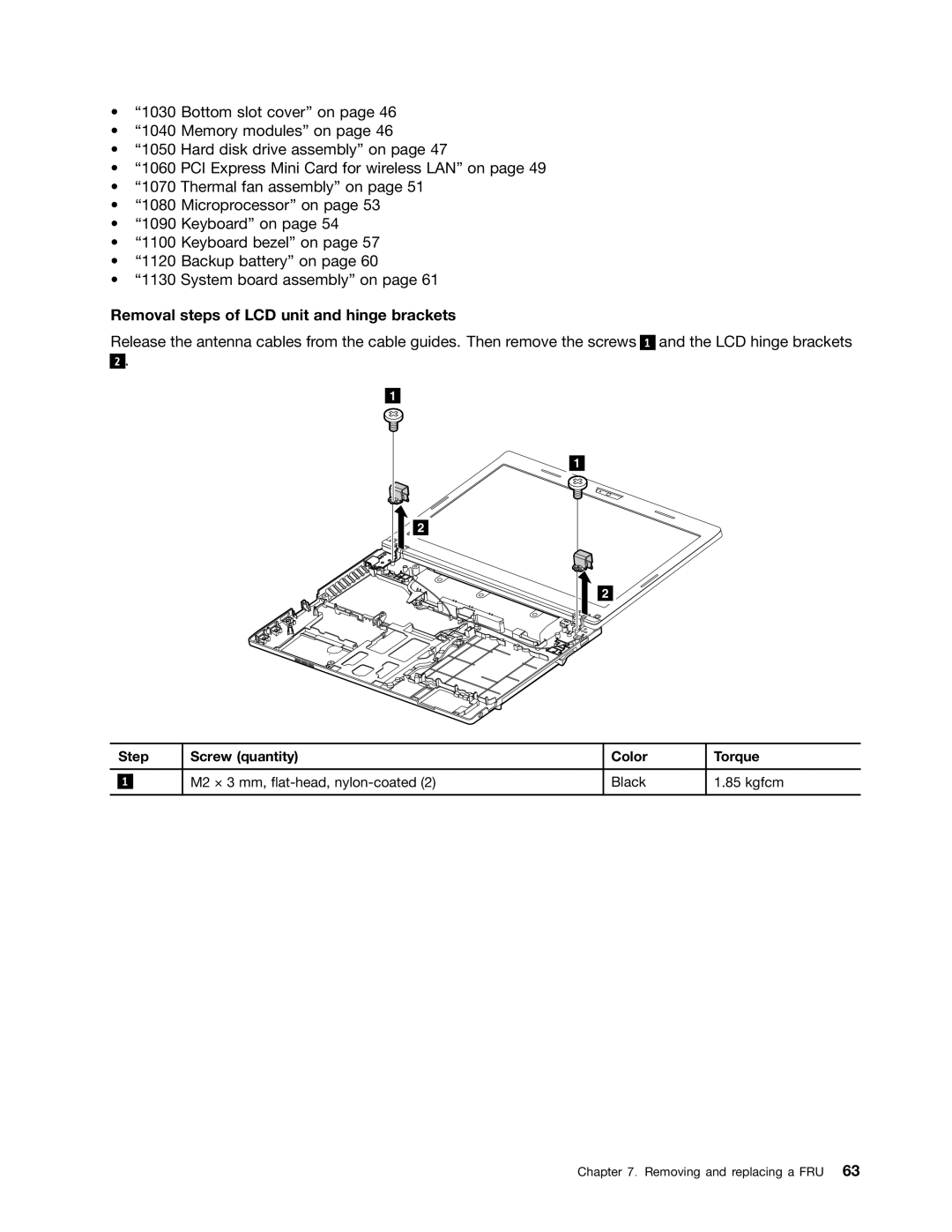
Removal steps of LCD unit and hinge brackets
Release the antenna cables from the cable guides. Then remove the screws
2.
1
1
![]()
![]() 2
2
2
1
and the LCD hinge brackets
| Step | Screw (quantity) | Color | Torque | |
|
|
|
|
|
|
|
|
| M2 × 3 mm, | Black | 1.85 kgfcm |
| 1 |
| |||
|
|
|
|
|
|
Chapter 7. Removing and replacing a FRU 63
