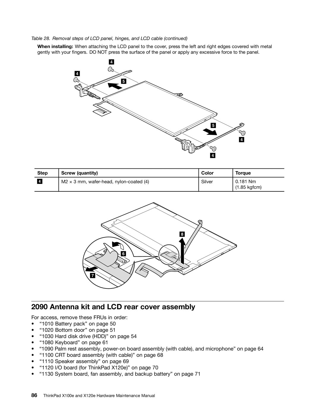
Table 28. Removal steps of LCD panel, hinges, and LCD cable (continued)
When installing: When attaching the LCD panel to the cover, press the left and right edges covered with metal gently with your fingers. DO NOT press the surface of the panel or apply any excessive force to the panel.
4
4
5
5
4
4
| Step | Screw (quantity) | Color | Torque | |
|
|
|
|
|
|
|
|
| M2 × 3 mm, | Silver | 0.181 Nm |
| 4 |
| |||
|
|
|
|
| (1.85 kgfcm) |
|
|
|
|
|
|
8
![]()
![]() 6
6
7
2090 Antenna kit and LCD rear cover assembly
For access, remove these FRUs in order:
•“1010 Battery pack” on page 50
•“1020 Bottom door” on page 51
•“1030 Hard disk drive (HDD)” on page 54
•“1080 Keyboard” on page 61
•“1090 Palm rest assembly,
•“1100 CRT board assembly (with cable)” on page 68
•“1110 Speaker assembly” on page 69
•“1120 I/O board (for ThinkPad X120e)” on page 70
•“1130 System board, fan assembly, and backup battery” on page 71
