Installation and 2
Installation and
Calibration
Calibration
Controls and
Indicators
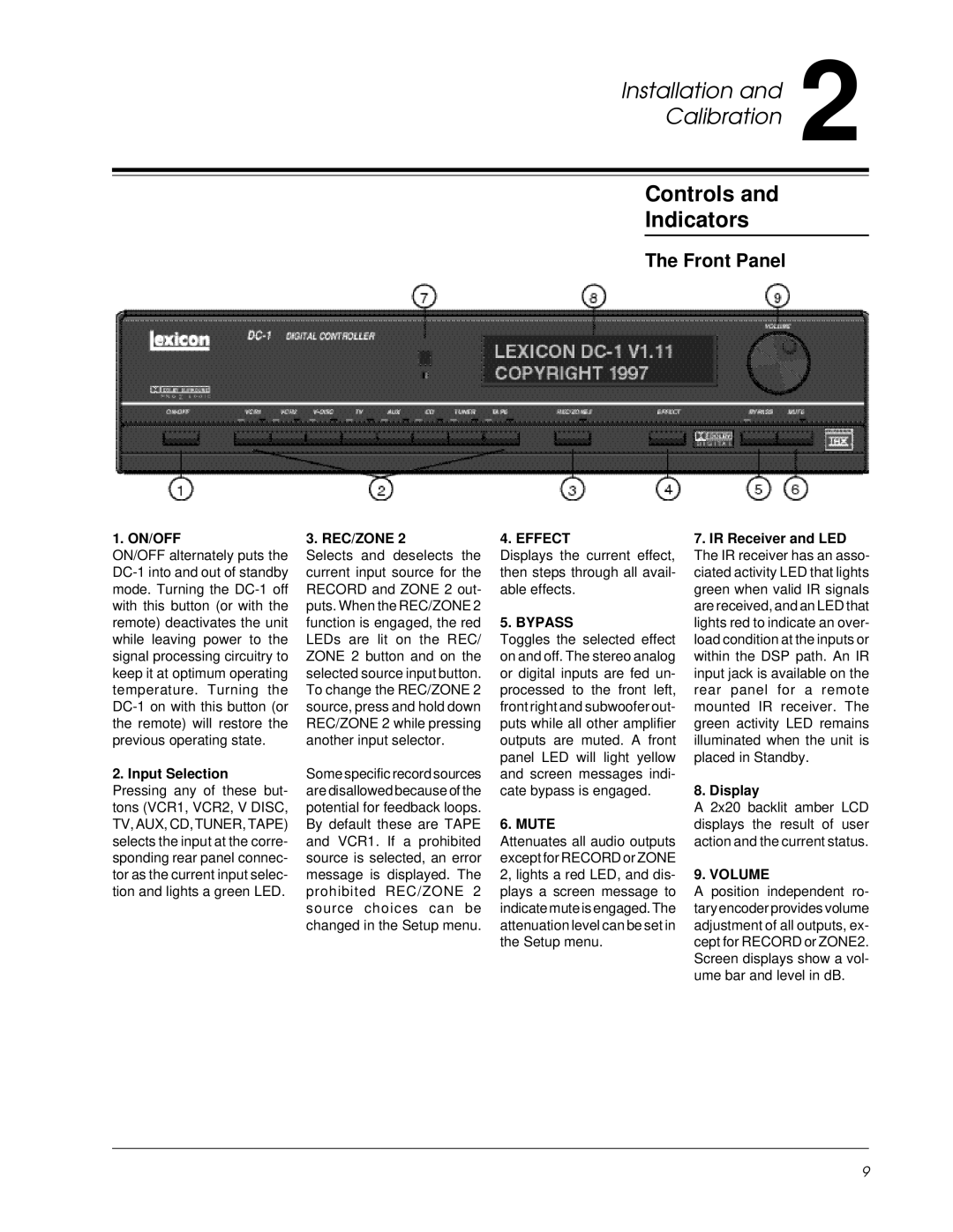
The Front Panel
1. ON/OFF
ON/OFF alternately puts the
2.Input Selection Pressing any of these but- tons (VCR1, VCR2, V DISC, TV, AUX, CD, TUNER, TAPE) selects the input at the corre- sponding rear panel connec- tor as the current input selec- tion and lights a green LED.
3. REC/ZONE 2
Selects and deselects the current input source for the RECORD and ZONE 2 out- puts. When the REC/ZONE 2 function is engaged, the red LEDs are lit on the REC/ ZONE 2 button and on the selected source input button. To change the REC/ZONE 2 source, press and hold down REC/ZONE 2 while pressing another input selector.
Some specific record sources are disallowed because of the potential for feedback loops. By default these are TAPE and VCR1. If a prohibited source is selected, an error message is displayed. The prohibited REC/ZONE 2 source choices can be changed in the Setup menu.
4. EFFECT
Displays the current effect, then steps through all avail- able effects.
5. BYPASS
Toggles the selected effect on and off. The stereo analog or digital inputs are fed un- processed to the front left, front right and subwoofer out- puts while all other amplifier outputs are muted. A front panel LED will light yellow and screen messages indi- cate bypass is engaged.
6. MUTE
Attenuates all audio outputs except for RECORD or ZONE 2, lights a red LED, and dis- plays a screen message to indicate mute is engaged. The attenuation level can be set in the Setup menu.
7.IR Receiver and LED The IR receiver has an asso- ciated activity LED that lights green when valid IR signals are received, and an LED that lights red to indicate an over- load condition at the inputs or within the DSP path. An IR input jack is available on the rear panel for a remote mounted IR receiver. The green activity LED remains illuminated when the unit is placed in Standby.
8.Display
A 2x20 backlit amber LCD displays the result of user action and the current status.
9. VOLUME
A position independent ro- tary encoder provides volume adjustment of all outputs, ex- cept for RECORD or ZONE2. Screen displays show a vol- ume bar and level in dB.
9