LED LCD TV
FCC Notice
Safety Instructions
Important Safety Instructions
Grounding
Outdoor antenna grounding
Only Hg lamp used LCD TV
Contents
Features of this TV
Accessories
Preparation
Protection Cover
42CQ610H
Preparation
Front Panel Information
Channel
Pillow Speaker Update Reset
Back Panel Information
Preparation
Antenna
Cable Management
External Equipment Setup section
With the included Protective Bracket
Install the Cable Management Clip as shown
Connect the cables as necessary
Inches
Wall Mount Installation
Kensington Security System
Inches
Vesa Wall Mounting
Quantity
Antenna or Cable Connection
Antenna Analog or Digital
HD Receiver Setup
Hdmi Connection
DVI to Hdmi Connection
DVD Setup
Instructions
Antenna Connection
VCR Setup
Wall Jack
Setup
Composite RCA Connection
Other A/V Source Setup
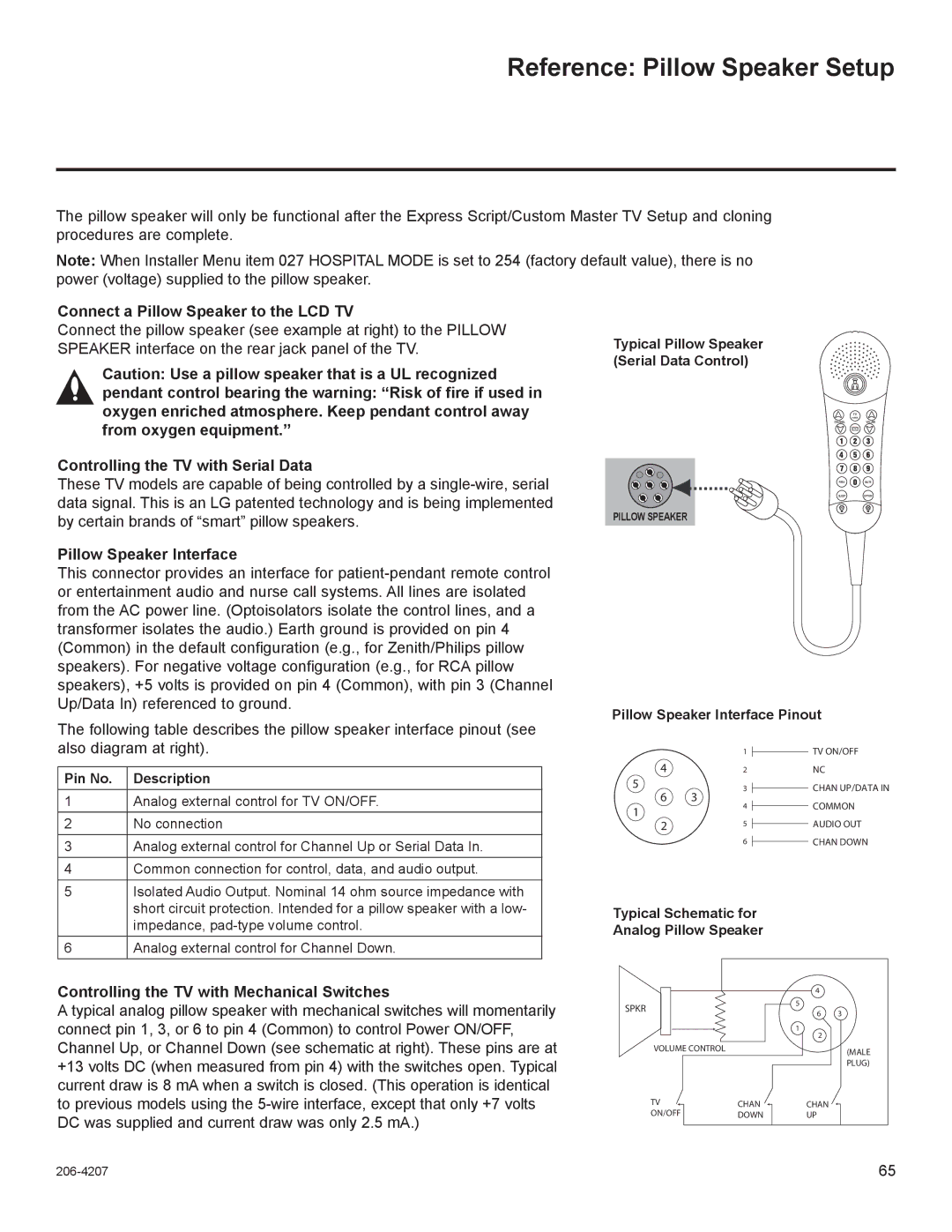
Pillow Speaker Setup
Controlling the TV with Serial Data
PC Setup
VGA D-Sub 15-pin Connection
RGB in PC
Select Resolution
Screen Setup for PC mode
Select Screen RGB-PC
Auto Configure
Select Auto config
Adjustment for screen Position, Size, and Phase
Select Position, Size, or Phase
Screen Reset Reset to original factory values
Turning on the TV
Volume Adjustment
Channel Selection
Select the Express Script
Initial Setting
Select Customize Inputs
Select Pillow Speaker Code
Select Edit channel map
ON-SCREEN Menus Selection
Audio
Select Auto Tuning
Channel Setup
Auto Scan Auto Tuning
Run Auto tuning
Select Manual Tuning
Add / Delete Channel Manual Tuning
Select Digital or Analog
Channel Editing
Select Channel Edit
Channel Label
Channel
Input List
Picture Size Aspect Ratio Control
Select Aspect Ratio
Set by program
169
Just Scan
Zoom
Picture Mode Preset
Preset Picture Settings
Select Picture Mode
Manual Picture Adjustment User Mode
Picture Improvement Technology
Select Advanced Control
Picture Control
Picture Reset
Select Picture Reset
Demo Mode
Select Demo Mode
Auto Volume Leveler Auto Volume
Select Auto Volume
Clear Voice
Adjustment for Clear Voice ll Level With selecting On
Select Clear Voice
Sound & Language Control
Balance
Select Sound Mode
Preset Sound Settings Sound Mode
Select Standard, Music Cinema, Sport, or Game
Sound Setting Adjustment User Mode
Select Standard, Music, Cinema, Sport, or Game
Infinite Sound
Select Infinite Sound
TV Speakers ON/OFF Setup
Select TV Speaker
Audio Reset
STEREO/SAP Broadcast Setup
Digital English, Spanish
Audio Language
Select Audio Language
ON-SCREEN Menus Language Selection
Select Menu Language
Analog Broadcasting System Captions
Caption Mode
Select CC1-4 or Text1-4
Select CC1-4,Text1-4, or Service1-6
Digital Broadcasting System Captions
Select Digital Option
Caption Option
Bg Background Color Select a
Bg Background Opacity Select
Auto Clock Setup
Clock Setting
Eastern, Central, Mountain, Pacific, Alaska, or Hawaii
Manual Clock Setup
Auto ON/OFF Time Setting
Select Off Time or On Time
Auto SHUT-OFF Setting
Sleep Timer Setting
Time menu
Enter the password as requested
SET Password & Lock System
Setting up Your Password
Select Lock
Select Lock System
Set Password
Select Set Password
Channel Blocking
Select Block Channel
Movie Rating Mpaa
Movie & TV Rating
Select Movie Rating
Select TV Rating-Children
TV Rating Children
Select Age or Fantasy Violence
Select TV Rating-General
TV Rating General
Select Lock Dialogue sexual dialogue Applies to TV-PG,TV-14
Violence
Downloadable Rating
What is shown in this manual
Password to unlock it temporarily
Select Downloadable Rating
External Input Blocking
Select Input Block
Entry Modes
Select Movie List, Photo List or Music List
MY Media
Movie List
Supported movie file
Supported Video Formats
Ts, trp, tp
Select Movie List
Screen Components
Move to Photo List
Mark Mode
Movie Selection
Photo List
Select Photo List
Photo Selection and Mark Mode
Photo List
Full Screen Menu
Option Set the Slide Speed and BGM
Select the Slideshow, BGM, Rotate, Option, or Hide
Music List
Select MY Media
Music Selection and Pop-up Menu
Music List
MY Media
Troubleshooting
Appendixp Endix
Audio does not work
Maintenance
Appendix
Product Specifications
22LQ630H 26LQ630H 22LQ630H-UA 26LQ630H-UA
Open Source License
GNU General Public License
Appendix
No Warranty
END of Terms and Conditions
GNU Lesser General Public License
100
101
102
103
104
Mozilla Public License
106
107
108
109
110
111
Apache License Version
113
114
115
BSD license strace
FreeType Project License
118
Jpeg license
MIT license
MIT/X11 style license Legion Of The Bouncy Castle
OpenSSL license
123
Zlib/libpng License
Model Serial
206-4207 Rev C
Copyright 2012, LG Electronics U.S.A., Inc
For Customer Support/Service, please call
Important Safety Instructions
Outdoor Antenna Grounding
Table of Contents
Setup Checklist
Commercial Mode Overview
Pass-through Mode
Installer Menu
External MPI Control
FTG Mode
Remote Management in FTG Mode
ProCentric Setup
ProCentric TV Interactive Menu Features
ProCentric Operation
Installer Remote Control Typical Key Functions
Mute
Express Script Installer Menu Wizard
Select the tuning band
Select the Aux inputs
Select the speaker configuration
Select the pillow speaker code
Run the Auto Search Auto Tuning
Edit the Channel Map
Completion
Icon
Before You Begin
Custom Master TV Setup
Clonable TV Setup Menu Features
Cloning Methods
Set Installer Menu items
Custom Master TV Setup Procedure
Set up TV features
Optional Run Auto Tuning
Channel
Set up channel banks
Verify the TV setup
Recommended Lock the channel lineup
Using the Installer Menu
Installer Menu
Accessing the Installer Menu
Exiting the Installer Menu and Activating Updates
Installer Menu Items 000 through
Strt Channel
Installer Menu Items 071 through
CH not Avble
Detailed Descriptions of Installer Menu Items
Installer Sequence
Sleep Timer
Poll Rate
Procentric
Power Savings
Channel Icons / Custom Text Labels 2-5-4 + Menu Mode
To perform channel editing/labeling
Accessing the Channel Preview/Banks Setup Menu
Channel Banks Setup
Channel Banks Overview
Channel Status Options
Inactive TV Setup
Channel Status Options for Channel Banks
Adding / Deleting / Blanking Channels
Example Channel Banks After Auto Tuning
Channel Banks Worksheets
Channel Banks Worksheet
Cloning Overview
Before you begin cloning
Learn Setup from Master TV
USB Cloning Procedures
USB Cloning Notes
Teach Master TV Setup to Target TV
Learn From TV TLL
Teach To TV TLL
Clone Programmer Cloning Procedures
TLL-1100A Cloning Notes
Optional Set the Clock
LT2002 Cloning Notes
LT2002 Clone Programmer
To Execute ITEM, Press ON/OFF, POWER, or Enter
FTG Mode via CPU
FTG Mode of Operation Overview
FTG Mode via CPU or EBL
FTG Mode via EBL
Determining the TV Operating Mode
Aspect Ratio
FTG Mode via CPU
From previous
Teaching FTG Configuration to a TV
Learning an FTG Configuration File from a TV
Optional Manual Configuration / TV Setup
Run Auto Tuning Channel Search
Jack Panel
FTG Mode via EBL Local Configuration
22LQ630H
26/32LQ630H
FTG File Manager Utilities Overview
FTG File Manager Main Screen
FTG Channel Map Configuration Utility
Print MAP
FTG Channel Map Editor
ADD Exit
FTG Installer Menu Configuration Utility
Configuration Settings
Checking the Software Versions
Upgrading TV/PTC Software
Splash Screen Image File Guidelines
Downloading a Splash Screen Image
Reference Power Consumption Settings
Static
Reference TV Aux Input Configuration
Enable
001 Default Off
Reference b-LAN Setup & Overview
TV Standby State TV Power On State
LAN & Game CONTROL/MPI Port
Hospital Features
Reference LQ630H/CQ610H Hospital Operations
Speaker Selection
Additional FTG Mode via CPU Options
Reference Resetting Factory Defaults on the TVs
Installer Menu Item 117 Fact Default
Additional FTG Mode via EBL Options
Reference TV Zone Restrictions
Reference 22LQ630H Rear and Side Jack Panels
USB
Reference 26/32LQ630H Rear and Side Jack Panels
HDMI/DVI
Reference 42CQ610H Rear and Side Jack Panels
Connect a Pillow Speaker to the LCD TV
Reference Pillow Speaker Setup
Controlling the TV with Mechanical Switches
Pillow Speaker Interface
USB Media
Wall Mounts
Reference Vesa Standard TV Mounts
Pedestal Mounts and Stands
Troubleshooting
Troubleshooting Flow Chart
Controller Quick Check
FTG Operation Troubleshooting
Commercial Mode Check / FTG Operation Troubleshooting
Symptom Possible Causes Solutions
Reset Clone Programmer After Static Shock
Clone Programmer Troubleshooting
Clone Programmer Symptom Possible Causes Possible Solutions
Channel Banks Setup Troubleshooting
Symptom Possible Cause Possible Solution
Reference Glossary of Terms
OHM RF Cable
Document Revision History
Document Revision History / Notes
Date Description
206-4207