Site Preparation
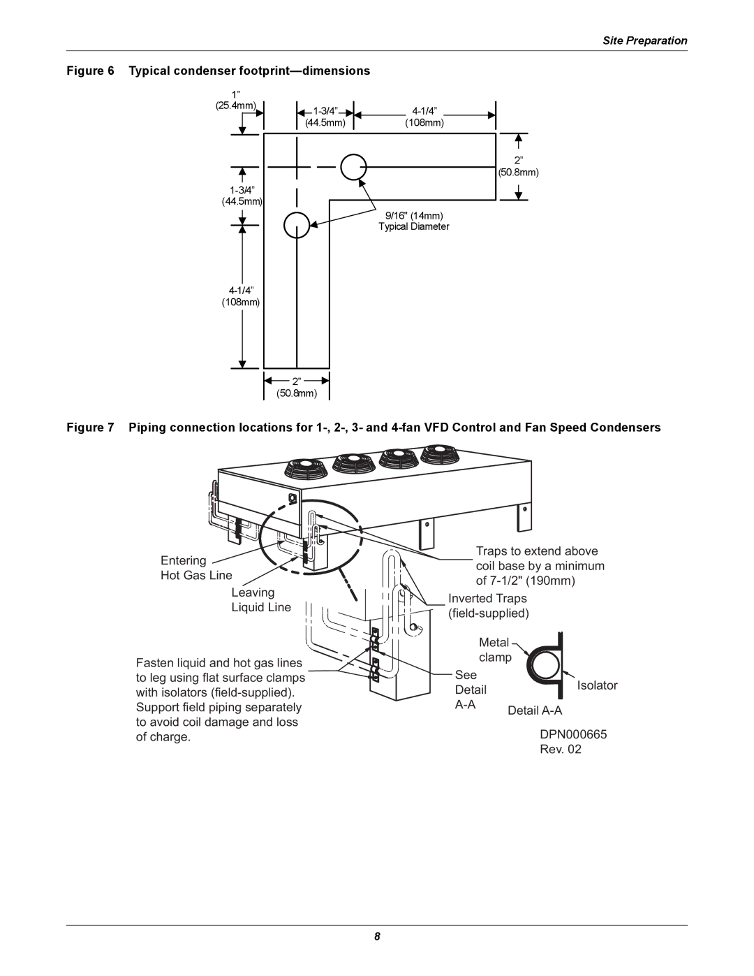
Figure 6 Typical condenser footprint—dimensions
1”
(25.4mm)
(44.5mm)
|
|
|
|
|
| ||
|
|
|
| ||||
(44.5mm) |
| (108mm) | |||||
2”
(50.8mm)
9/16" (14mm) Typical Diameter
2”
(50.8mm)
Figure 7 Piping connection locations for 1-, 2-, 3- and 4-fan VFD Control and Fan Speed Condensers
Entering ![]()
![]()
![]()
Hot Gas Line
Leaving
Liquid Line
Fasten liquid and hot gas lines ![]() to leg using flat surface clamps
to leg using flat surface clamps ![]() with isolators
with isolators
Support field piping separately to avoid coil damage and loss of charge.
Traps to extend above coil base by a minimum of
Inverted Traps
Metal clamp
See | Isolator |
Detail | |
Detail | |
| |
| DPN000665 |
| Rev. 02 |
8
