Inspection and Installation
3.9.2Field Piping Installation
One discharge line and one liquid line must be
NOTE
Keep the evaporator unit and condenser closed with their factory charge of dry nitrogen while all field piping is installed. Keep the field piping clean and dry during installation, and do not allow it to stand open to the atmosphere.
When all the field interconnecting piping is in place, vent the condenser’s dry nitrogen charge and connect to the field piping. Finally, vent the evaporator unit’s dry nitrogen charge and make its piping connections last.
Follow all proper brazing practices, including a dry nitrogen purge to maintain system cleanliness.
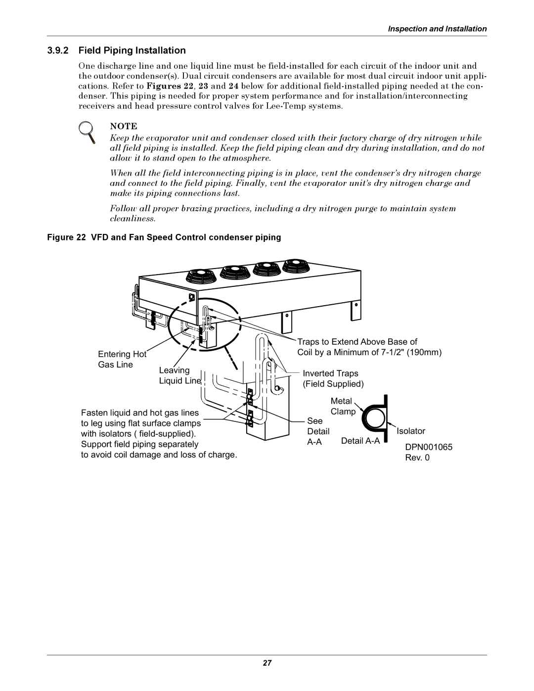
Figure 22 VFD and Fan Speed Control condenser piping
Entering Hot
Gas Line
Leaving
Liquid Line
Fasten liquid and hot gas lines to leg using flat surface clamps with isolators (
Support field piping separately
to avoid coil damage and loss of charge.
Traps to Extend Above Base of
Coil by a Minimum of
Inverted Traps
(Field Supplied)
| Metal | |
See | Clamp | |
Isolator | ||
Detail | ||
Detail | ||
| DPN001065 | |
| Rev. 0 |
27