Operation
4.0OPERATION
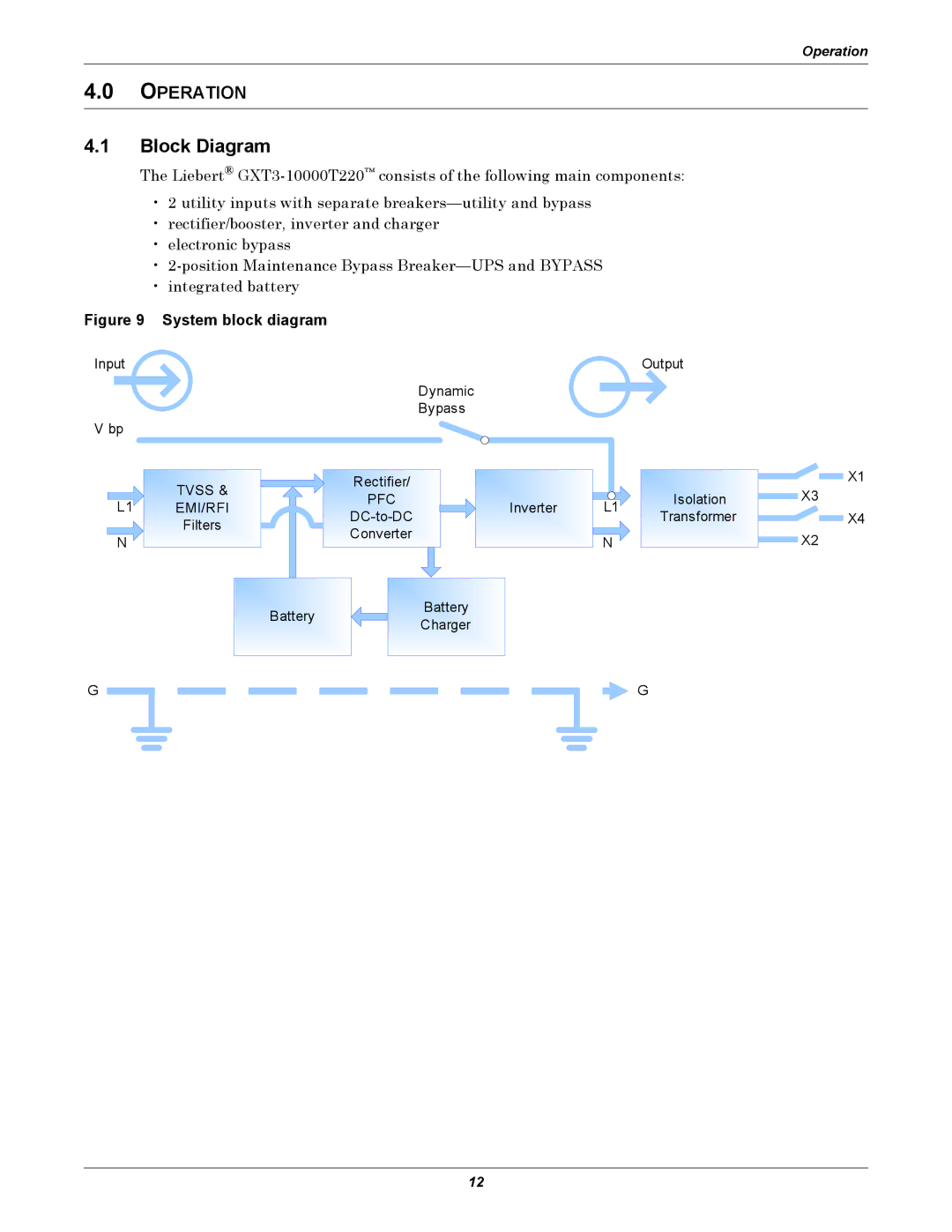
4.1Block Diagram
The Liebert®
•2 utility inputs with separate
•rectifier/booster, inverter and charger
•electronic bypass
•
•integrated battery
Figure 9 System block diagram
Input | Output |
Dynamic
Bypass
V bp
TVSS & | Rectifier/ |
|
| Isolation | |
PFC |
| L1 | |||
EMI/RFI | Inverter | ||||
Transformer | |||||
Filters |
|
| |||
Converter |
| N |
| ||
|
|
| |||
|
|
|
| ||
| Battery | Battery |
|
| |
| Charger |
|
| ||
|
|
|
|
![]()
![]() X1
X1
X3
![]()
![]() X4
X4
X2
G
![]() G
G
12