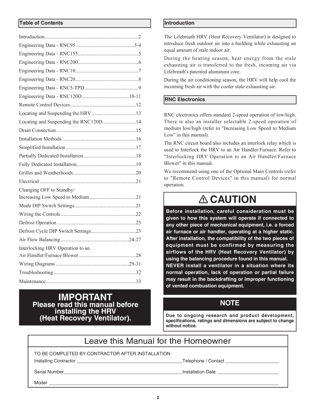
RNC155, RNC20, RNC95, RNC120D, RNC10 specifications
Lifebreath is renowned for its commitment to providing high-quality air ventilation products that enhance indoor air quality. Among its popular models are the RNC95, RNC5-TPD, RNC155, RNC10, and RNC200, each offering unique features and technologies tailored to different ventilation needs.The Lifebreath RNC95 is known for its efficient performance, featuring a high-efficiency heat exchanger that recovers up to 95% of the energy from outgoing air. This model is perfect for residential use, where energy efficiency is paramount. The compact design allows for easy installation, and it is equipped with advanced controls that enable smart operation, ensuring optimal air quality with minimal energy consumption.
On the other hand, the RNC5-TPD is designed for tight spaces without compromising on performance. It provides a versatile solution with a variable speed motor that adjusts airflow to match the specific requirements of the environment. This model also features a quick-change filter system, making maintenance a breeze. Its energy recovery capabilities help reduce heating and cooling costs, appealing to eco-conscious consumers.
The RNC155 stands out due to its robust capacity, catering to larger living spaces or commercial environments. This unit integrates advanced airflow management technology, allowing users to balance air distribution effectively throughout the building. The unit's energy-efficient operation is complemented by integrated controls that can be programmed for optimal performance based on occupancy and air quality levels.
The RNC10 offers a budget-friendly option while maintaining effective ventilation. It is compact and lightweight, making it ideal for smaller rooms or apartments. Despite its size, it features a reliable heat recovery system that significantly lowers energy costs and enhances comfort.
Finally, the RNC200 is a powerhouse model designed for larger commercial spaces. It boasts an impressive airflow capacity, making it suitable for demanding environments. This unit includes sophisticated monitoring systems that provide real-time data on air quality and system performance, ensuring that the air remains fresh and healthy. Additionally, its customizable setup allows for integration with other HVAC systems, further enhancing its functionality.
In summary, Lifebreath models like RNC95, RNC5-TPD, RNC155, RNC10, and RNC200 exemplify cutting-edge ventilation technology. Their distinct features cater to various needs, from residential to commercial applications, ensuring that users enjoy optimal indoor air quality while minimizing energy expenditure.

