Installation
USING PASSIVE CROSSOVERS
A passive crossover is a circuit that uses capacitors and/or coils and is placed on speaker leads between the amplifier and speaker. The crossover delegates a specific range of frequencies to the speaker for optimum driver performance. A crossover network can perform one of three functions:
The most commonly used passive crossover networks are 6dB/octave systems. These are easy to construct and require one component per filter. Placing this filter in series with the circuit will reduce power to the speaker by 6dB/octave above or below the crossover point depending on whether it is a
Passive crossovers are directly dependent upon the speaker's impedance and component value for accuracy. When passive crossover components are used in multiple speaker systems, the crossover's effect on the overall impedance should be taken into consideration along with the speaker's impedance when determining amplifier loads.
|
|
|
|
|
|
|
|
|
|
|
|
|
|
|
|
|
|
|
|
|
|
|
|
|
|
|
|
|
|
|
|
|
|
|
|
|
|
|
|
| L |
|
|
|
|
|
|
|
|
| C |
|
|
|
|
| |||
|
|
|
|
|
|
|
|
|
|
|
|
|
|
|
|
|
|
|
|
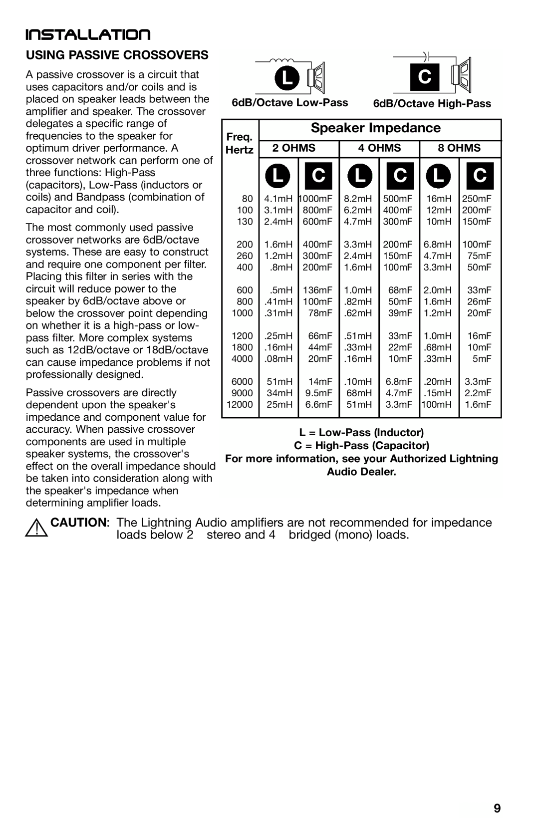
6dB/Octave | 6dB/Octave | ||||||||||||||||||
|
|
|
|
|
|
|
|
|
|
|
|
|
|
|
|
|
|
| |
Freq. |
|
| Speaker Impedance |
|
|
| |||||||||||||
|
|
|
|
|
|
|
|
|
|
|
|
|
|
|
|
|
|
| |
Hertz | 2 OHMS | 4 OHMS |
|
|
| 8 OHMS | |||||||||||||
| L |
| C |
| L |
|
| C |
|
|
| L |
| C |
| ||||
80 | 4.1mH | 1000mF | 8.2mH |
| 500mF |
|
| 16mH | 250mF | ||||||||||
100 | 3.1mH | 800mF | 6.2mH |
| 400mF |
|
| 12mH | 200mF | ||||||||||
130 | 2.4mH | 600mF | 4.7mH |
| 300mF |
|
| 10mH | 150mF | ||||||||||
200 | 1.6mH | 400mF | 3.3mH |
| 200mF |
| 6.8mH | 100mF | |||||||||||
260 | 1.2mH | 300mF | 2.4mH |
| 150mF |
| 4.7mH |
| 75mF | ||||||||||
400 | .8mH | 200mF | 1.6mH |
| 100mF |
| 3.3mH |
| 50mF | ||||||||||
600 | .5mH | 136mF | 1.0mH |
|
| 68mF |
| 2.0mH |
| 33mF | |||||||||
800 | .41mH | 100mF | .82mH |
|
| 50mF |
| 1.6mH |
| 26mF | |||||||||
1000 | .31mH |
| 78mF | .62mH |
|
| 39mF |
| 1.2mH |
| 20mF | ||||||||
1200 | .25mH |
| 66mF | .51mH |
|
| 33mF |
| 1.0mH |
| 16mF | ||||||||
1800 | .16mH |
| 44mF | .33mH |
|
| 22mF |
| .68mH |
| 10mF | ||||||||
4000 | .08mH |
| 20mF | .16mH |
|
| 10mF |
| .33mH |
| 5mF | ||||||||
6000 | 51mH |
| 14mF | .10mH |
| 6.8mF |
| .20mH | 3.3mF | ||||||||||
9000 | 34mH |
| 9.5mF | 68mH |
| 4.7mF |
| .15mH | 2.2mF | ||||||||||
12000 | 25mH |
| 6.6mF | 51mH |
| 3.3mF |
| 100mH | 1.6mF | ||||||||||
|
|
|
|
|
|
|
|
|
|
|
|
|
|
|
|
|
|
|
|
L =
C =
For more information, see your Authorized Lightning
Audio Dealer.
!CAUTION: The Lightning Audio amplifiers are not recommended for impedance loads below 2Ω stereo and 4Ω bridged (mono) loads.
9