OPERATION |
WIRE WELDING-CV
Connect a wire feeder to the AIR VANTAGE® 500 KUBOTA according to the instructions in INSTALLATION INSTRUC- TIONS Section.
The AIR VANTAGE® 500 KUBOTA in the
NOTE: In the
ARC GOUGING
The AIR VANTAGE® 500 KUBOTA can be used for arc gouging.
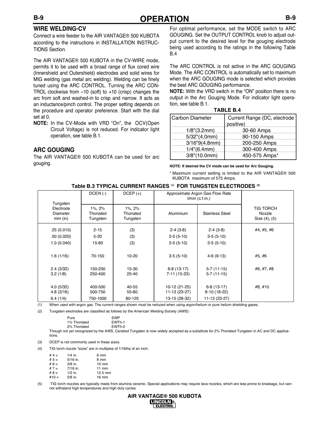
For optimal performance, set the MODE switch to ARC GOUGING. Set the OUTPUT CONTROL knob to adjust out- put current to the desired level for the gouging electrode being used according to the ratings in the following Table B.4
The ARC CONTROL is not active in the ARC GOUGING Mode. The ARC CONTROL is automatically set to maximum when the ARC GOUGING mode is selected which provides the best ARC GOUGING performance.
NOTE: With the VRD switch in the “ON” position there is no output in the Arc Gouging Mode. For indicator light opera- tion, see table B.1.
TAbLE b.4
| Carbon Diameter | Current Range (DC, electrode | |
|
| positive) |
|
| 1/8"(3.2mm) | ||
| 5/32"(4.0mm) | ||
| 3/16"9(4.8mm) | Amps | |
| 1/4"(6.4mm) | Amps | |
| 3/8"(10.0mm) | Amps* | |
|
|
|
|
NOTE: If desired the CV mode can be used for Arc Gouging.
*Maximum current setting is limited to the AIR VANTAGE® 500 KUBOTA maximum of 575 Amps.
|
| Table b.3 TYPICAL CURRENT RANGES (1) | FOR TUNGSTEN ELECTRODES (2) | ||||||
|
|
| DCEN | DCEP (+) | Approximate Argon Gas Flow Rate |
| |||
|
|
|
|
|
| l/min (c.f.m.) |
|
| |
Tungsten |
|
|
|
|
|
|
|
| |
Electrode |
| 1%, 2% | 1%, 2% |
|
|
|
| TIG TORCH | |
Diameter |
| Thoriated | Thoriated | Aluminium | Stainless Steel | Nozzle | |||
mm (in) |
| Tungsten | Tungsten |
|
|
|
| Size (4), (5) | |
|
|
|
|
|
|
|
|
| |
.25 | (0.010) |
| (3) | #4, #5, #6 | |||||
.50 | (0.020) |
| (3) |
| |||||
1.0 | (0.040) |
| (3) |
| |||||
1.6 | (1/16) |
| #5, #6 | ||||||
2.4 | (3/32) |
| #6, #7, #8 | ||||||
3.2 | (1/8) |
|
| ||||||
4.0 | (5/32) |
| #8, #10 | ||||||
4.8 | (3/16) |
|
| ||||||
6.4 | (1/4) |
|
|
|
|
| |||
(1)When used with argon gas. The current ranges shown must be reduced when using argon/helium or pure helium shielding gases.
(2)Tungsten electrodes are classified as follows by the American Welding Society (AWS):
Pure | EWP |
1% Thoriated | |
2% Thoriated |
Though not yet recognized by the AWS, Ceriated Tungsten is now widely accepted as a substitute for 2% Thoriated Tungsten in AC and DC applica- tions.
(3)DCEP is not commonly used in these sizes.
(4)TIG torch nozzle “sizes” are in multiples of 1/16ths of an inch:
# 4 = | 1/4 in. | 6 mm |
# 5 = | 5/16 in. | 8 mm |
# 6 = | 3/8 in. | 10 mm |
# 7 = | 7/16 in. | 11 mm |
# 8 = | 1/2 in. | 12.5 mm |
#10 = | 5/8 in. | 16 mm |
(5)TIG torch nozzles are typically made from alumina ceramic. Special applications may require lava nozzles, which are less prone to breakage, but can- not withstand high temperatures and high duty cycles.
AIR VANTAGE® 500 KUbOTA