OPERATION | ||
|
|
|
1
2
3
4
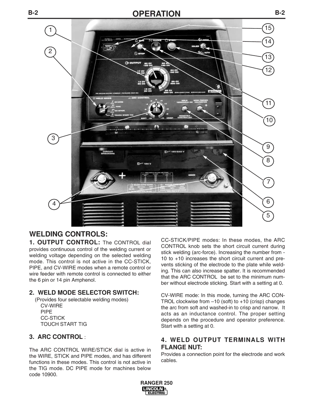
WELDING CONTROLS:
1. OUTPUT CONTROL: The CONTROL dial provides continuous control of the welding current or welding voltage depending on the selected welding mode. This control is not active in the
2. WELD MODE SELECTOR SWITCH:
(Provides four selectable welding modes)
CV-WIRE PIPE CC-STICK TOUCH START TIG
![]() 15 14
15 14
![]() 13
13
![]() 12
12
11
10
9
8
7
6
5
3. ARC CONTROL :
The ARC CONTROL WIRE/STICK dial is active in the WIRE, STICK and PIPE modes, and has different functions in these modes. This control is not active in the TIG mode. DC PIPE mode for machines below code 10900.
4.WELD OUTPUT TERMINALS WITH FLANGE NUT:
Provides a connection point for the electrode and work cables.
RANGER 250