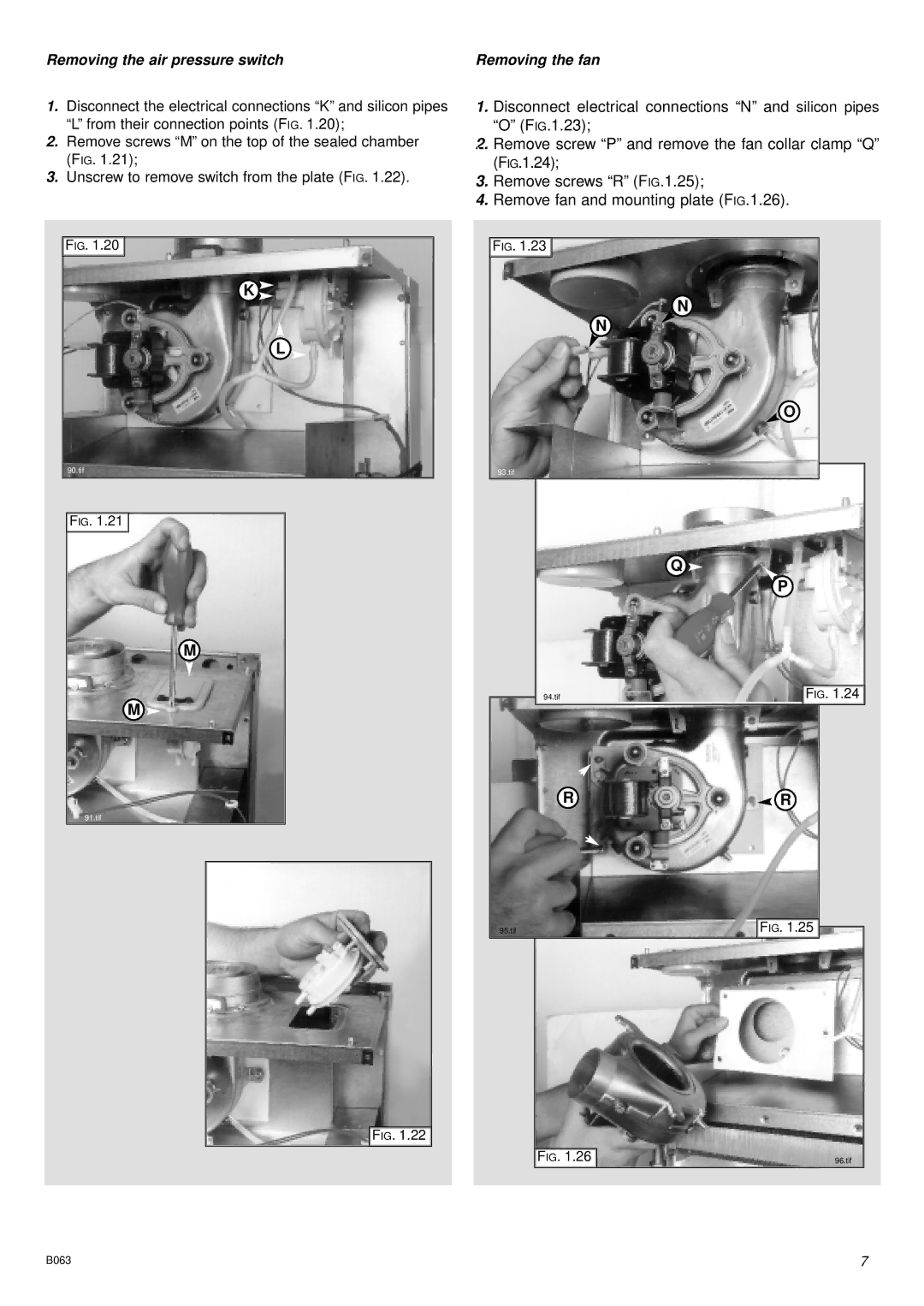
Removing the air pressure switch
1.Disconnect the electrical connections “K” and silicon pipes “L” from their connection points (FIG. 1.20);
2.Remove screws “M” on the top of the sealed chamber (FIG. 1.21);
3.Unscrew to remove switch from the plate (FIG. 1.22).
FIG. 1.20 ![]()
![]()
K ![]()
L
90.tif
FIG. 1.21 ![]()
![]()
M
M ![]()
91.tif
![]()
![]() FIG. 1.22
FIG. 1.22
Removing the fan
1.Disconnect electrical connections “N” and silicon pipes “O” (FIG.1.23);
2.Remove screw “P” and remove the fan collar clamp “Q” (FIG.1.24);
3.Remove screws “R” (FIG.1.25);
4.Remove fan and mounting plate (FIG.1.26).
FIG. 1.23 ![]()
![]()
N
N
![]() O
O
93.tif
Q ![]()
P
94.tif | FIG. 1.24 |
R![]() R
R
95.tif | FIG. 1.25 |
FIG. 1.26 | 96.tif |
B063 | 7 |