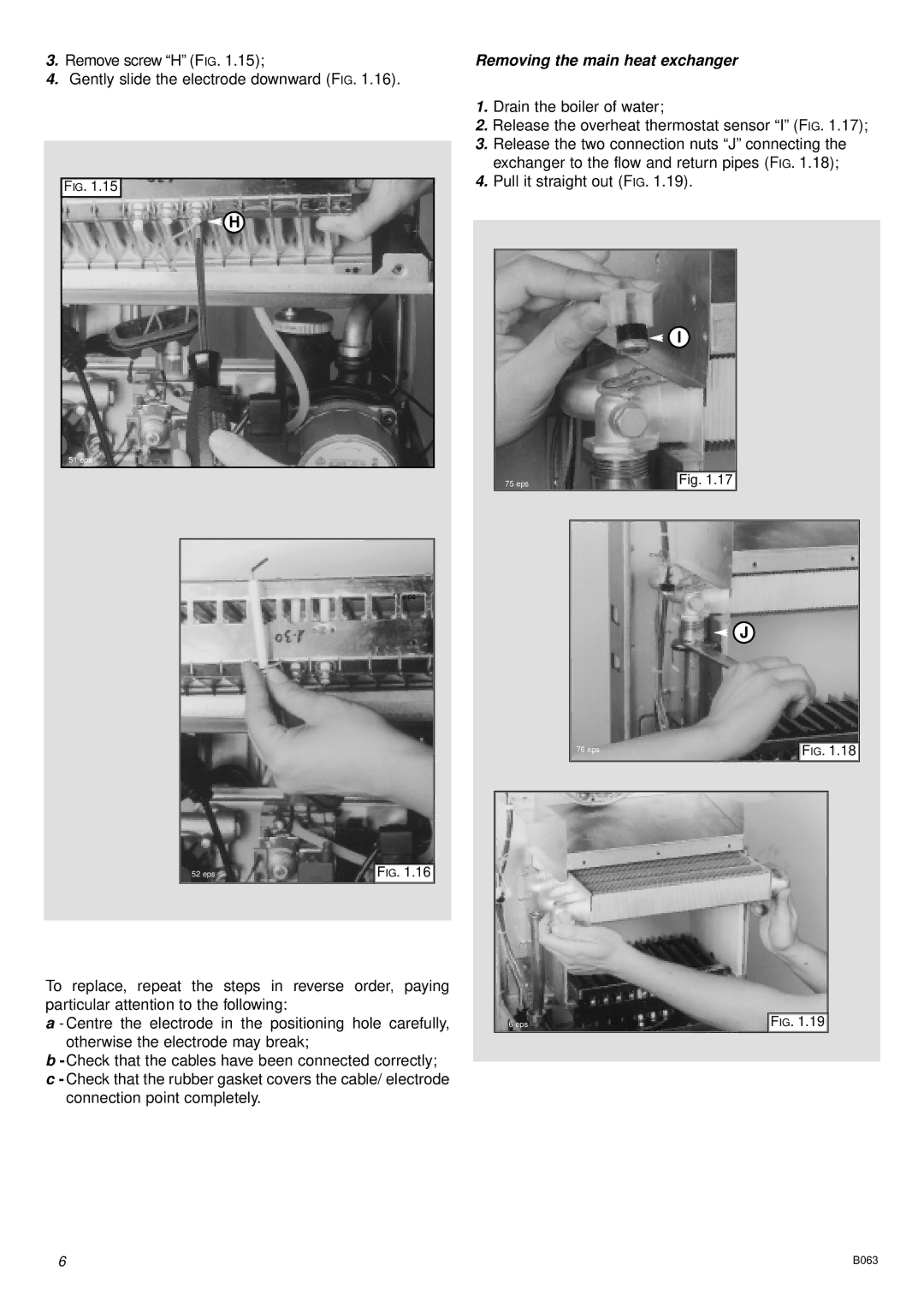
3.Remove screw “H” (FIG. 1.15);
4.Gently slide the electrode downward (FIG. 1.16).
FIG. 1.15
![]() H
H
51 eps
11 eps
52 eps | FIG. 1.16 |
To replace, repeat the steps in reverse order, paying particular attention to the following:
a - Centre the electrode in the positioning hole carefully, otherwise the electrode may break;
b
c- Check that the rubber gasket covers the cable/ electrode connection point completely.
Removing the main heat exchanger
1.Drain the boiler of water;
2.Release the overheat thermostat sensor “I” (FIG. 1.17);
3.Release the two connection nuts “J” connecting the exchanger to the flow and return pipes (FIG. 1.18);
4.Pull it straight out (FIG. 1.19).
I
75 eps | Fig. 1.17 |
J
76 eps | FIG. 1.18 |
|
|
6 eps | FIG. 1.19 |
6 | B063 |
