1.3ACCESS TO THE COMBUSTION CHAMBER
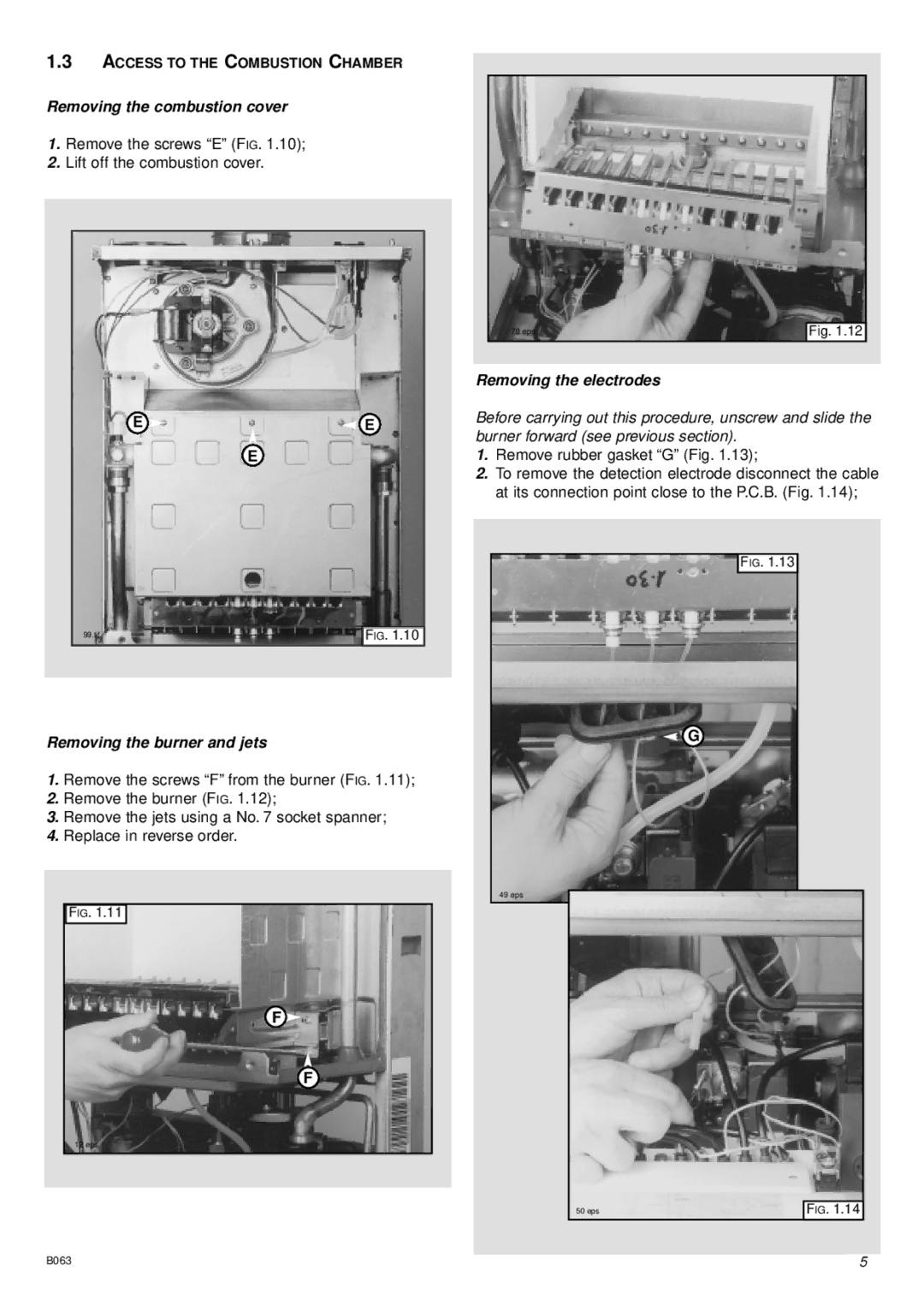
Removing the combustion cover
1.Remove the screws “E” (FIG. 1.10);
2.Lift off the combustion cover.
E | E |
| E |
99.tif | FIG. 1.10 |
Removing the burner and jets
1.Remove the screws “F” from the burner (FIG. 1.11);
2.Remove the burner (FIG. 1.12);
3.Remove the jets using a No. 7 socket spanner;
4.Replace in reverse order.
FIG. 1.11
F ![]()
F
12 eps
|
|
|
|
|
|
|
|
| 78 eps | Fig. 1.12 |
|
|
|
|
|
Removing the electrodes
Before carrying out this procedure, unscrew and slide the burner forward (see previous section).
1.Remove rubber gasket “G” (Fig. 1.13);
2.To remove the detection electrode disconnect the cable at its connection point close to the P.C.B. (Fig. 1.14);
FIG. 1.13
G
49 eps
50 eps | FIG. 1.14 |
B063 | 5 |
