OPERATION | ||
|
|
|
CONSTANT VOLTAGE WELDING
Non Synergic CV:
This type of CV mode behaves more like a conventional CV power source. Voltage and WFS are independent adjustments. Therefore to maintain the arc characteristics, the operator must adjust the voltage to compensate for any changes made to the WFS.
All CV Modes:
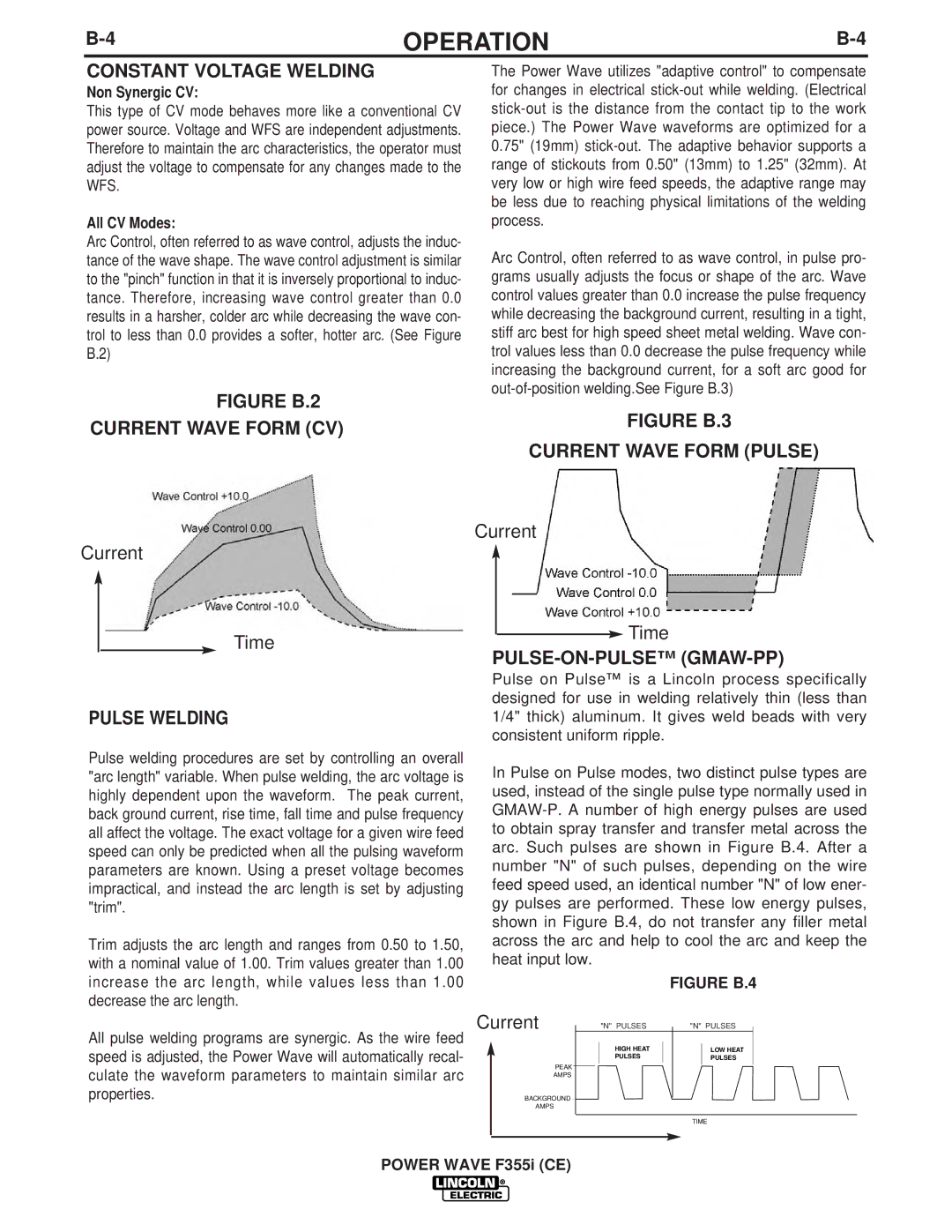
Arc Control, often referred to as wave control, adjusts the induc- tance of the wave shape. The wave control adjustment is similar to the "pinch" function in that it is inversely proportional to induc- tance. Therefore, increasing wave control greater than 0.0 results in a harsher, colder arc while decreasing the wave con- trol to less than 0.0 provides a softer, hotter arc. (See Figure B.2)
FIGURE B.2
CURRENT WAVE FORM (CV)
Current
Time
PULSE WELDING
Pulse welding procedures are set by controlling an overall "arc length" variable. When pulse welding, the arc voltage is highly dependent upon the waveform. The peak current, back ground current, rise time, fall time and pulse frequency all affect the voltage. The exact voltage for a given wire feed speed can only be predicted when all the pulsing waveform parameters are known. Using a preset voltage becomes impractical, and instead the arc length is set by adjusting "trim".
Trim adjusts the arc length and ranges from 0.50 to 1.50, with a nominal value of 1.00. Trim values greater than 1.00 increase the arc length, while values less than 1.00 decrease the arc length.
All pulse welding programs are synergic. As the wire feed speed is adjusted, the Power Wave will automatically recal- culate the waveform parameters to maintain similar arc properties.
The Power Wave utilizes "adaptive control" to compensate for changes in electrical
Arc Control, often referred to as wave control, in pulse pro- grams usually adjusts the focus or shape of the arc. Wave control values greater than 0.0 increase the pulse frequency while decreasing the background current, resulting in a tight, stiff arc best for high speed sheet metal welding. Wave con- trol values less than 0.0 decrease the pulse frequency while increasing the background current, for a soft arc good for
FIGURE B.3
CURRENT WAVE FORM (PULSE)
Current
Time
PULSE-ON-PULSE™ (GMAW-PP)
Pulse on Pulse™ is a Lincoln process specifically designed for use in welding relatively thin (less than 1/4" thick) aluminum. It gives weld beads with very consistent uniform ripple.
In Pulse on Pulse modes, two distinct pulse types are used, instead of the single pulse type normally used in
FIGURE B.4
Current | "N" PULSES | "N" PULSES |
| HIGH HEAT | LOW HEAT |
| PULSES | PULSES |
PEAK |
|
|
AMPS |
|
|
BACKGROUND |
|
|
AMPS |
|
|
|
| TIME |