OPERATION | ||
|
|
|
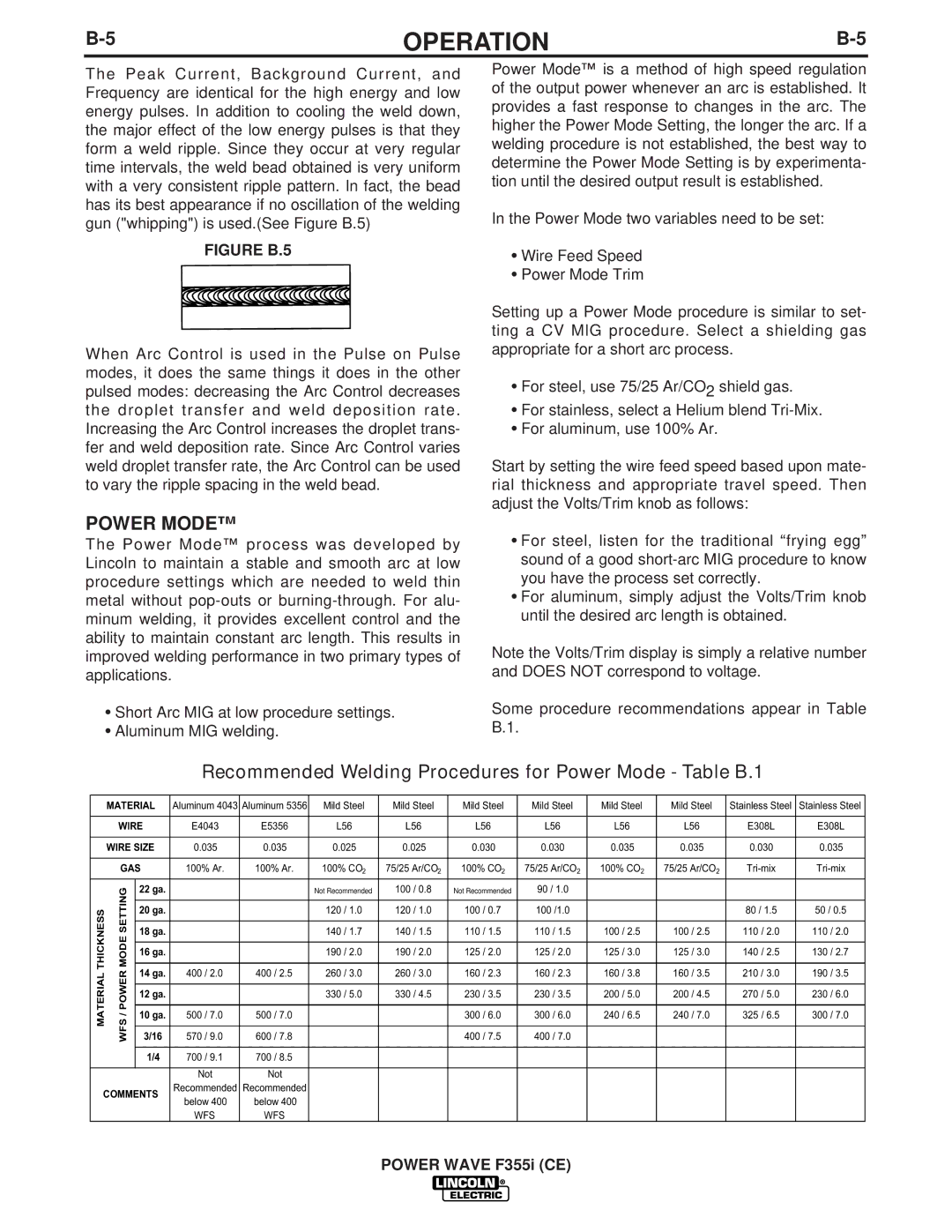
The Peak Current, Background Current, and Frequency are identical for the high energy and low energy pulses. In addition to cooling the weld down, the major effect of the low energy pulses is that they form a weld ripple. Since they occur at very regular time intervals, the weld bead obtained is very uniform with a very consistent ripple pattern. In fact, the bead has its best appearance if no oscillation of the welding gun ("whipping") is used.(See Figure B.5)
FIGURE B.5
When Arc Control is used in the Pulse on Pulse modes, it does the same things it does in the other pulsed modes: decreasing the Arc Control decreases the droplet transfer and weld deposition rate. Increasing the Arc Control increases the droplet trans- fer and weld deposition rate. Since Arc Control varies weld droplet transfer rate, the Arc Control can be used to vary the ripple spacing in the weld bead.
Power Mode™ is a method of high speed regulation of the output power whenever an arc is established. It provides a fast response to changes in the arc. The higher the Power Mode Setting, the longer the arc. If a welding procedure is not established, the best way to determine the Power Mode Setting is by experimenta- tion until the desired output result is established.
In the Power Mode two variables need to be set:
•Wire Feed Speed
•Power Mode Trim
Setting up a Power Mode procedure is similar to set- ting a CV MIG procedure. Select a shielding gas appropriate for a short arc process.
•For steel, use 75/25 Ar/CO2 shield gas.
•For stainless, select a Helium blend
•For aluminum, use 100% Ar.
Start by setting the wire feed speed based upon mate- rial thickness and appropriate travel speed. Then adjust the Volts/Trim knob as follows:
POWER MODE™
The Power Mode™ process was developed by Lincoln to maintain a stable and smooth arc at low procedure settings which are needed to weld thin metal without
•Short Arc MIG at low procedure settings.
•Aluminum MIG welding.
•For steel, listen for the traditional “frying egg” sound of a good
•For aluminum, simply adjust the Volts/Trim knob until the desired arc length is obtained.
Note the Volts/Trim display is simply a relative number and DOES NOT correspond to voltage.
Some procedure recommendations appear in Table B.1.
Recommended Welding Procedures for Power Mode - Table B.1
| MATERIAL | Aluminum 4043 | Aluminum 5356 | Mild Steel | Mild Steel | Mild Steel | Mild Steel | Mild Steel | Mild Steel | Stainless Steel | Stainless Steel | |
|
|
|
|
|
|
|
|
|
|
|
| |
| WIRE | E4043 | E5356 | L56 | L56 | L56 | L56 | L56 | L56 | E308L | E308L | |
|
|
|
|
|
|
|
|
|
|
|
| |
| WIRE SIZE | 0.035 | 0.035 | 0.025 | 0.025 | 0.030 | 0.030 | 0.035 | 0.035 | 0.030 | 0.035 | |
|
|
|
|
|
|
|
|
|
|
|
| |
| GAS | 100% Ar. | 100% Ar. | 100% CO2 | 75/25 Ar/CO2 | 100% CO2 | 75/25 Ar/CO2 | 100% CO2 | 75/25 Ar/CO2 | |||
|
|
|
|
|
|
|
|
|
|
|
|
|
THICKNESS | SETTINGMODE | 22 ga. |
|
| Not Recommended | 100 / 0.8 | Not Recommended | 90 / 1.0 |
|
|
|
|
|
|
|
|
|
|
|
|
|
|
|
|
|
|
| 20 ga. |
|
| 120 / 1.0 | 120 / 1.0 | 100 / 0.7 | 100 /1.0 |
|
| 80 / 1.5 | 50 / 0.5 |
|
|
|
|
|
|
|
|
|
|
|
|
|
|
| 18 ga. |
|
| 140 / 1.7 | 140 / 1.5 | 110 / 1.5 | 110 / 1.5 | 100 / 2.5 | 100 / 2.5 | 110 / 2.0 | 110 / 2.0 |
|
|
|
|
|
|
|
|
|
|
|
|
|
|
| 16 ga. |
|
| 190 / 2.0 | 190 / 2.0 | 125 / 2.0 | 125 / 2.0 | 125 / 3.0 | 125 / 3.0 | 140 / 2.5 | 130 / 2.7 |
|
|
|
|
|
|
|
|
|
|
|
|
|
MATERIAL | /WFSPOWER | 14 ga. | 400 / 2.0 | 400 / 2.5 | 260 / 3.0 | 260 / 3.0 | 160 / 2.3 | 160 / 2.3 | 160 / 3.8 | 160 / 3.5 | 210 / 3.0 | 190 / 3.5 |
|
|
|
|
|
|
|
|
|
|
| ||
3/16 | 570 / 9.0 | 600 / 7.8 | 330 / 5.0 | 330 / 4.5 | 400 / 7.5 | 400 / 7.0 | 200 / 5.0 | 200 / 4.5 | 270 / 5.0 | 230 / 6.0 | ||
|
| 12 ga. |
|
| 230 / 3.5 | 230 / 3.5 | ||||||
|
| 10 ga. | 500 / 7.0 | 500 / 7.0 |
|
| 300 / 6.0 | 300 / 6.0 | 240 / 6.5 | 240 / 7.0 | 325 / 6.5 | 300 / 7.0 |
|
|
|
|
|
|
|
|
|
|
|
|
|
|
| 1/4 | 700 / 9.1 | 700 / 8.5 |
|
|
|
|
|
|
|
|
|
|
|
|
|
|
|
|
|
|
|
|
|
|
|
| Not | Not |
|
|
|
|
|
|
|
|
COMMENTS | Recommended | Recommended |
|
|
|
|
|
|
|
| ||
below 400 | below 400 |
|
|
|
|
|
|
|
| |||
|
|
|
|
|
|
|
|
|
|
| ||
|
|
| WFS | WFS |
|
|
|
|
|
|
|
|