9 – Start-Up, Shutdown and Bypass
1
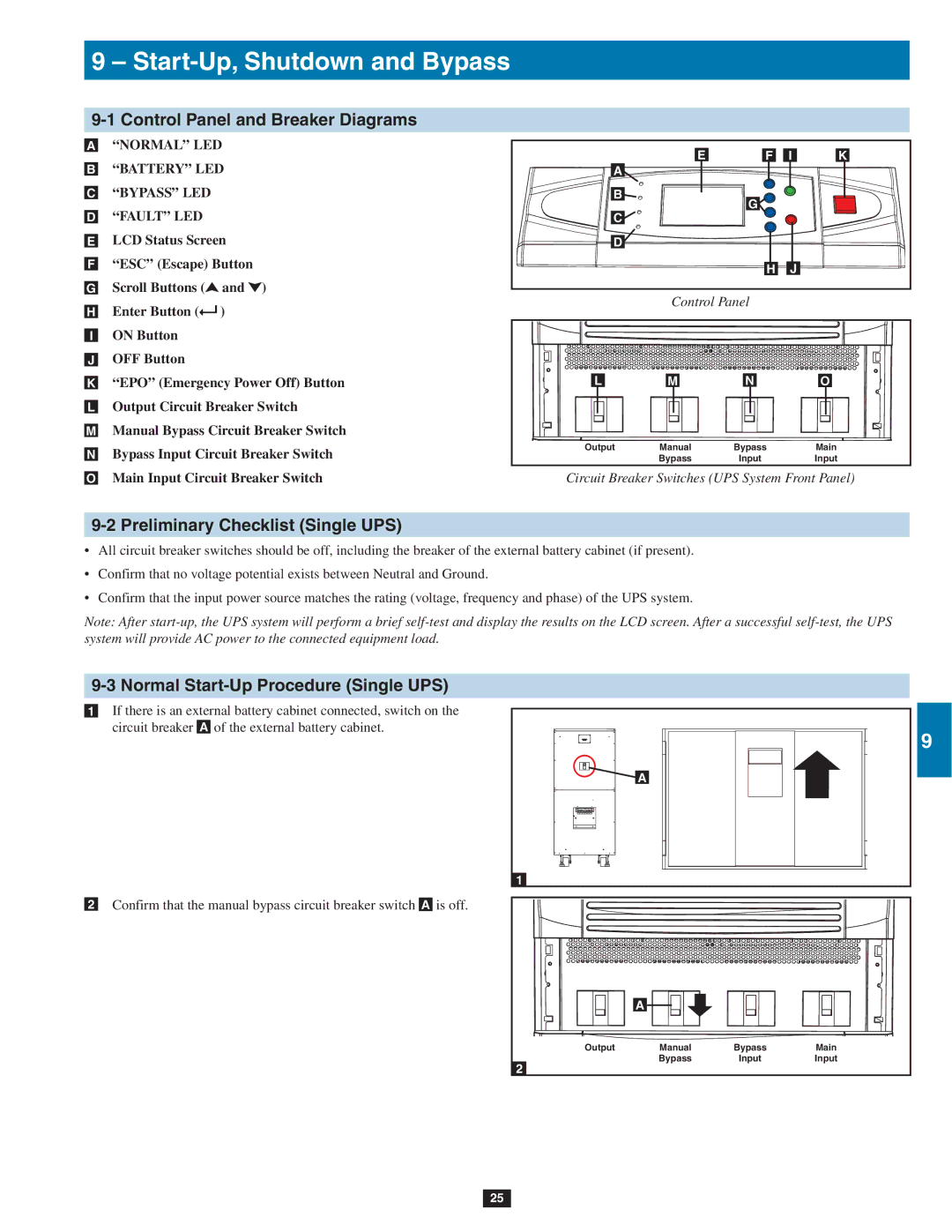
9-1 Control Panel and Breaker Diagrams
•A “NORMAL” LED
•B “BATTERY” LED
•C “BYPASS” LED
•D “FAULT” LED
•E LCD Status Screen
•F “ESC” (Escape) Button
•G Scroll Buttons (![]() and
and ![]() )
)
•H Enter Button (![]() )
)
•I ON Button
•J OFF Button
•K “EPO” (Emergency Power Off) Button
•L Output Circuit Breaker Switch
•M Manual Bypass Circuit Breaker Switch
•N Bypass Input Circuit Breaker Switch
•O Main Input Circuit Breaker Switch
E | F | I | K | 2 |
A |
|
|
| |
B | G |
|
|
|
C |
|
|
| |
|
|
|
| |
D |
|
|
| 3 |
|
|
|
| |
| H | J |
|
|
Control Panel
4
L | M | N | O |
|
|
| 5 |
Output | Manual | Bypass | Main |
| Bypass | Input | Input |
Circuit Breaker Switches (UPS System Front Panel)
6
9-2 Preliminary Checklist (Single UPS)
• All circuit breaker switches should be off, including the breaker of the external battery cabinet (if present).
• Confirm that no voltage potential exists between Neutral and Ground.7
• Confirm that the input power source matches the rating (voltage, frequency and phase) of the UPS system.
Note: After
9-3 Normal Start-Up Procedure (Single UPS)
•1 If there is an external battery cabinet connected, switch on the circuit breaker A of the external battery cabinet.
8 |
9 |
A |
10 |
1 |
•2 Confirm that the manual bypass circuit breaker switch A is off.
|
|
| 11 |
| A |
| 12 |
|
|
| |
Output | Manual | Bypass | Main |
| Bypass | Input | Input |
2 |
|
| 13 |
|
|
| 14 |
25