10 – Display and Configuration
1
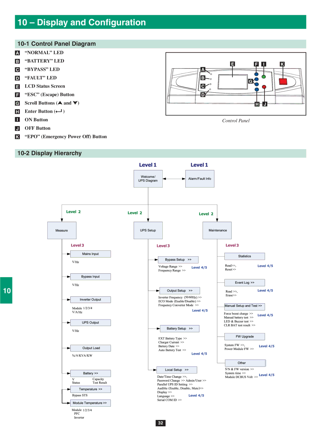
10-1 Control Panel Diagram
•A “NORMAL” LED
2 •B “BATTERY” LED
•C “BYPASS” LED
•D “FAULT” LED
3 •E LCD Status Screen
•F “ESC” (Escape) Button
•G Scroll Buttons (![]() and
and ![]() )
)
•H Enter Button (![]() )
)
4•I ON Button
•J OFF Button
•K “EPO” (Emergency Power Off) Button
5
10-2 Display Hierarchy
6
7
8
9
10
11
12
13
14
E | F | I | K |
A |
|
|
|
B | G |
|
|
C |
|
| |
|
|
| |
D |
|
|
|
| H | J |
|
Control Panel
32