7 – Wiring (continued)
| 1 |
|
|
|
|
Warning: External battery cabinets vary. Read the external battery cabinet’s documentation before attempting to connect it to the UPS | 2 |
system. Use only external battery cabinets that have been approved by Tripp Lite. |
Note: An external battery cabinet is required with models SU60K, SU60KTV and SU80KTV. It is optional with model SU40K. Contact Tripp Lite for external battery cabinet ordering information.
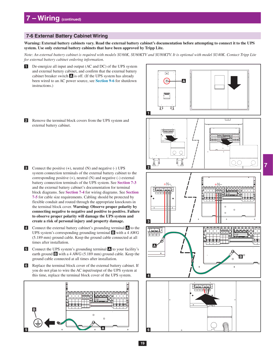
•1
cabinet breaker switch A is off. (If the UPS system has already been wired to an AC power source, see Section
•2 Remove the terminal block covers from the UPS system and external battery cabinet.
•3 Connect the positive (+), neutral (N) and negative
•4 Connect the external battery cabinet’s grounding terminal A to the UPS system’s corresponding grounding terminal B with a 4 AWG (5.189 mm) ground cable. Keep the ground cable connected at all times after installation.
•5 Connect the UPS system’s grounding terminal A to your facility’s earth ground B with a 4 AWG (5.189 mm) ground cable. Keep the ground cable connected at all times after installation.
•6 Replace the terminal block cover of the external battery cabinet. If you do not plan to wire the AC input/output of the UPS system at this time, replace the terminal block cover of the UPS system.
| B |
5 | A |
|
|
| 3 |
| A |
|
|
| 4 |
1 |
| 5 |
|
| |
|
| 6 |
2 |
| 7 |
+N– | +N– | 8 |
|
| |
|
| 9 |
3 |
|
|
|
| 10 |
A |
|
|
| B | 11 |
|
| |
4 |
|
|
|
| 12 |
|
| 13 |
6 |
| 14 |
19
