9 – Start-Up, Shutdown and Bypass (continued)
1
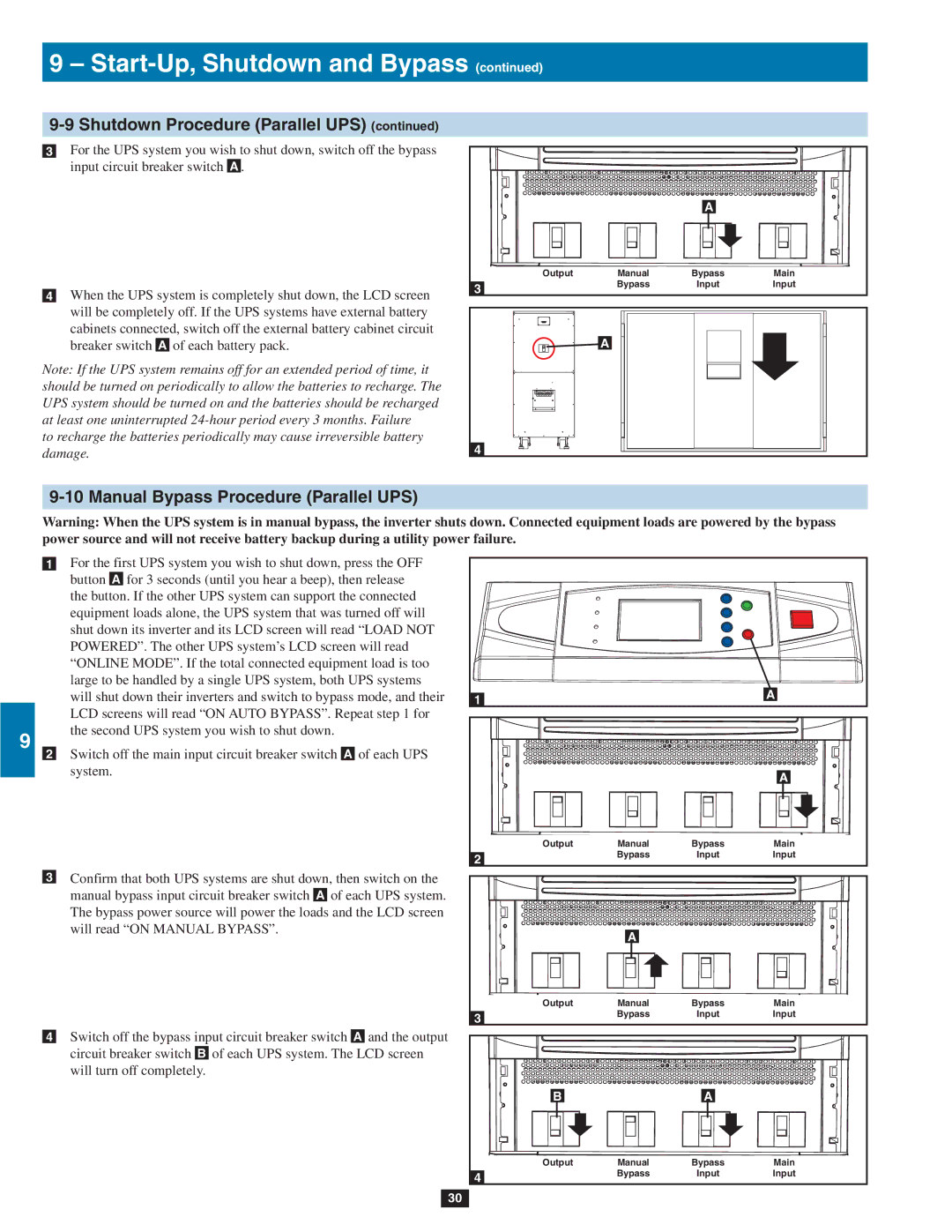
9-9 Shutdown Procedure (Parallel UPS) (continued)
•3 For the UPS system you wish to shut down, switch off the bypass
2input circuit breaker switch A .
3
•4 When the UPS system is completely shut down, the LCD screen will be completely off. If the UPS systems have external battery
4cabinets connected, switch off the external battery cabinet circuit breaker switch A of each battery pack.
Note: If the UPS system remains off for an extended period of time, it should be turned on periodically to allow the batteries to recharge. The UPS system should be turned on and the batteries should be recharged
5at least one uninterrupted
|
| A |
|
Output | Manual | Bypass | Main |
3 | Bypass | Input | Input |
|
|
|
A |
4 |
69-10 Manual Bypass Procedure (Parallel UPS)
Warning: When the UPS system is in manual bypass, the inverter shuts down. Connected equipment loads are powered by the bypass power source and will not receive battery backup during a utility power failure.
•1 For the first UPS system you wish to shut down, press the OFF
7button A for 3 seconds (until you hear a beep), then release the button. If the other UPS system can support the connected
equipment loads alone, the UPS system that was turned off will shut down its inverter and its LCD screen will read “LOAD NOT POWERED”. The other UPS system’s LCD screen will read
8“ONLINE MODE”. If the total connected equipment load is too large to be handled by a single UPS system, both UPS systems will shut down their inverters and switch to bypass mode, and their LCD screens will read “ON AUTO BYPASS”. Repeat step 1 for
9 |
|
| the second UPS system you wish to shut down. | ||||||||
|
|
|
|
|
|
|
|
|
|
| |
| •2 | Switch off the main input circuit breaker switch | A | of each UPS | |||||||
|
| ||||||||||
|
|
| system. | ||||||||
|
|
|
|
|
|
|
|
|
|
|
|
10 |
|
|
|
|
|
|
|
|
|
|
|
|
|
|
|
|
|
|
|
|
|
|
|
|
|
|
|
|
|
|
|
|
|
|
|
|
| •3 | Confirm that both UPS systems are shut down, then switch on the | ||||||||
|
|
| manual bypass input circuit breaker switch |
| of each UPS system. | ||||||
11 |
|
| A | ||||||||
|
| The bypass power source will power the loads and the LCD screen | |||||||||
|
|
| will read “ON MANUAL BYPASS”. | ||||||||
|
|
|
|
|
|
|
|
|
|
|
|
|
|
|
|
|
|
|
|
|
|
|
|
12 |
|
|
|
|
|
|
|
|
|
|
|
|
|
| Switch off the bypass input circuit breaker switch |
|
| and the output | |||||
|
|
|
| ||||||||
| A | ||||||||||
|
| •4 | |||||||||
|
|
| circuit breaker switch |
| of each UPS system. The LCD screen | ||||||
13 |
|
| B | ||||||||
|
| will turn off completely. | |||||||||
|
|
|
|
|
|
|
|
|
|
|
|
|
|
|
|
|
|
|
|
|
|
|
|
14 |
|
|
|
|
|
|
|
|
|
|
|
|
|
|
|
|
|
|
|
|
|
|
|
1 | A |
|
|
|
| A |
Output | Manual | Bypass | Main |
2 | Bypass | Input | Input |
|
|
|
| A |
|
|
Output | Manual | Bypass | Main |
3 | Bypass | Input | Input |
|
|
|
B |
| A |
|
Output | Manual | Bypass | Main |
4 | Bypass | Input | Input |
|
|
|
30