9 – Start-Up, Shutdown and Bypass (continued)
1
9-3 Normal Start-Up Procedure (Single UPS) (continued)
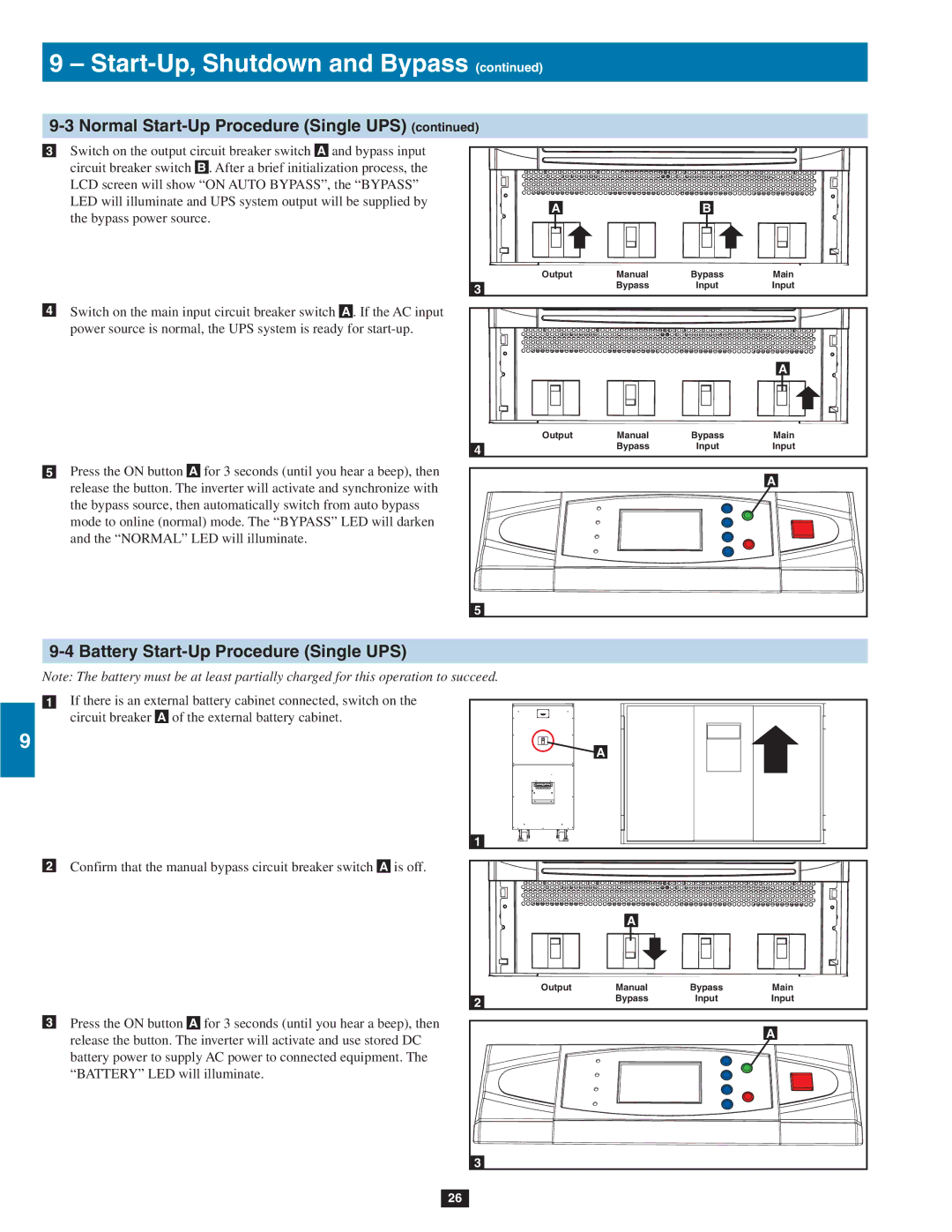
•3 Switch on the output circuit breaker switch A and bypass input
2circuit breaker switch B . After a brief initialization process, the LCD screen will show “ON AUTO BYPASS”, the “BYPASS” LED will illuminate and UPS system output will be supplied by the bypass power source.
3
•4 Switch on the main input circuit breaker switch A . If the AC input
4power source is normal, the UPS system is ready for
5
•5 Press the ON button A for 3 seconds (until you hear a beep), then
6release the button. The inverter will activate and synchronize with the bypass source, then automatically switch from auto bypass mode to online (normal) mode. The “BYPASS” LED will darken and the “NORMAL” LED will illuminate.
7
A |
| B |
|
Output | Manual | Bypass | Main |
3 | Bypass | Input | Input |
|
|
|
|
|
| A |
Output | Manual | Bypass | Main |
4 | Bypass | Input | Input |
|
|
| |
|
|
| A |
5
89-4 Battery Start-Up Procedure (Single UPS)
Note: The battery must be at least partially charged for this operation to succeed.
•1 If there is an external battery cabinet connected, switch on the circuit breaker A of the external battery cabinet.
9
10
•2 Confirm that the manual bypass circuit breaker switch A is off.
11
12
•3 Press the ON button A for 3 seconds (until you hear a beep), then release the button. The inverter will activate and use stored DC battery power to supply AC power to connected equipment. The
13 “BATTERY” LED will illuminate.
![]() A
A
1 |
|
|
|
| A |
|
|
Output | Manual | Bypass | Main |
2 | Bypass | Input | Input |
|
|
| |
|
|
| A |
14
3
26