|
| OPERATION |
|
| ||
| FIGURE B.3 |
|
|
| ||
|
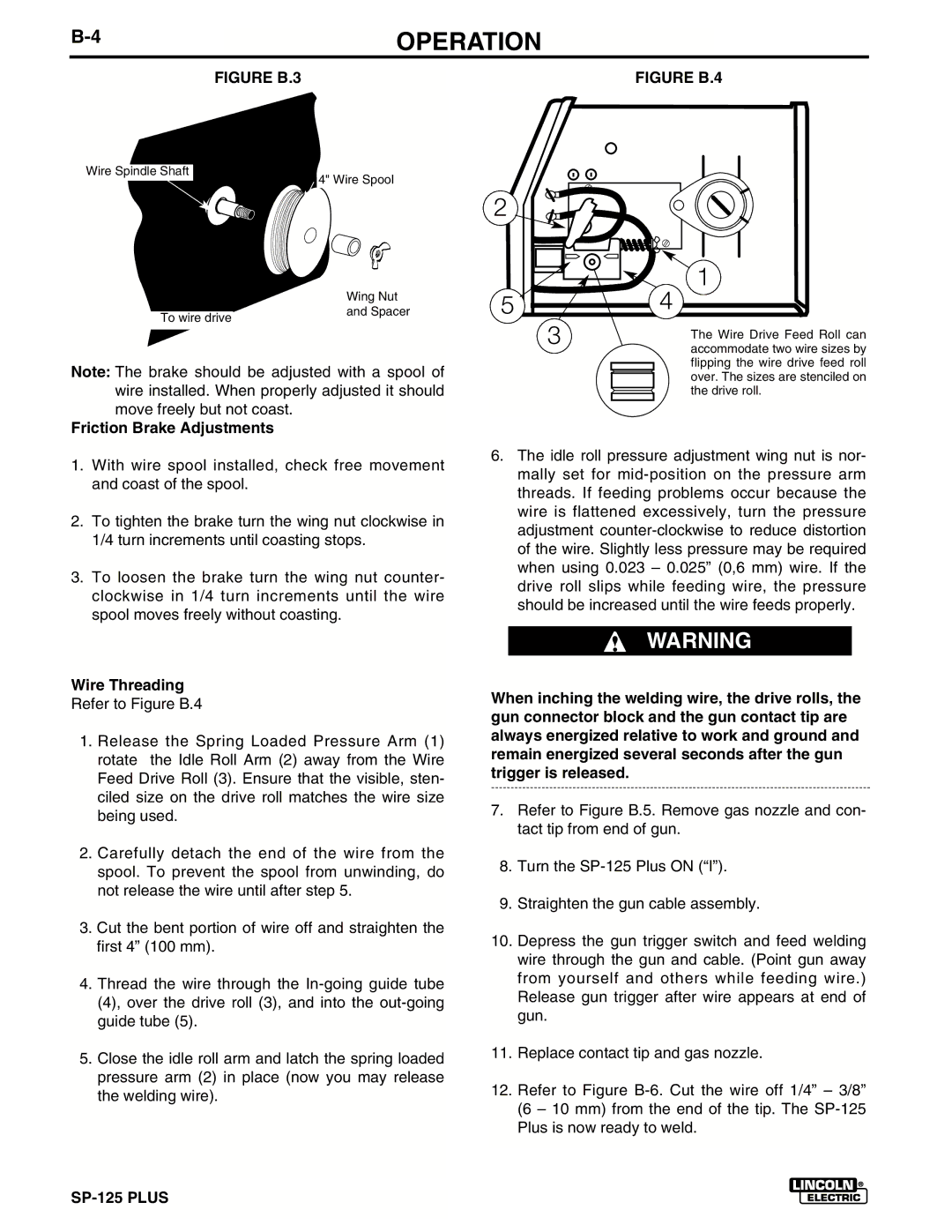
| FIGURE B.4 | ||||
|
|
|
|
|
|
|
Wire Spindle Shaft
4" Wire Spool
|
|
|
|
|
|
| Wing Nut |
|
|
| and Spacer |
| To wire drive |
| |
|
|
| |
|
|
|
|
Note: The brake should be adjusted with a spool of wire installed. When properly adjusted it should move freely but not coast.
Friction Brake Adjustments
1.With wire spool installed, check free movement and coast of the spool.
2.To tighten the brake turn the wing nut clockwise in 1/4 turn increments until coasting stops.
3.To loosen the brake turn the wing nut counter- clockwise in 1/4 turn increments until the wire spool moves freely without coasting.
Wire Threading
Refer to Figure B.4
1.Release the Spring Loaded Pressure Arm (1) rotate the Idle Roll Arm (2) away from the Wire Feed Drive Roll (3). Ensure that the visible, sten- ciled size on the drive roll matches the wire size being used.
2.Carefully detach the end of the wire from the spool. To prevent the spool from unwinding, do not release the wire until after step 5.
3.Cut the bent portion of wire off and straighten the first 4” (100 mm).
4.Thread the wire through the
5.Close the idle roll arm and latch the spring loaded pressure arm (2) in place (now you may release the welding wire).
2
|
| 1 |
5 | 3 | 4 |
| The Wire Drive Feed Roll can | |
|
| |
|
| accommodate two wire sizes by |
|
| flipping the wire drive feed roll |
|
| over. The sizes are stenciled on |
|
| the drive roll. |
6.The idle roll pressure adjustment wing nut is nor- mally set for
WARNING
When inching the welding wire, the drive rolls, the gun connector block and the gun contact tip are always energized relative to work and ground and remain energized several seconds after the gun trigger is released.
7.Refer to Figure B.5. Remove gas nozzle and con- tact tip from end of gun.
8.Turn the
9.Straighten the gun cable assembly.
10.Depress the gun trigger switch and feed welding wire through the gun and cable. (Point gun away from yourself and others while feeding wire.) Release gun trigger after wire appears at end of gun.
11.Replace contact tip and gas nozzle.
12.Refer to Figure