INSTALLATION | ||
|
|
|
GAS INPUT CONNECTIONS
Supply the
•Supply pressure must be between 80 psi(5.6kg/cm2) and 120 psi(8.4kg/cm2).
•Pressure gage, located on the front of the machine, should be set to approximately 70 psi(4.9kg/cm2) for a 25ft.(7.6m) torch and 75 psi(5.3kg/cm2) for a 50 ft.(15.2m) torch while gas is flowing (purging or cut- ting).
•Flow rate should be approximately 8.0 cfm (227 I/min.).
NOTE: Oil in the air supply to the
•Connect the gas supply to the
•Compressed gas should be supplied to the fitting connection mounted on the filter at the rear of the machine. If necessary, this fitting can be removed allowing plumbing access through the 1/4” NPT input port on the filter body.
•If compressed air is being used, it is highly recom- mended that an inline prefilter be installed in the air supply line ahead of the air connection to the PRO- CUT’s coalescing filter. While the coalescing filter is used to remove small amounts of oil and water aerosol particles from the air supply line, the prefilter can be used to remove larger particulates before they reach the coalescing filter element. This will prolong the life of the coalescing filter element by up to six times what it would be without the prefilter, and in turn, prolong the life of the
•A standard nominal 5 micron inline prefilter is recom- mended; however, for optimum performance, select a prefilter with a 3 micron absolute rating. If these fil- ter ratings are unavailable, anything with a rating less than, or equal to, 20 micron would be accept- able to use. In line filter elements will generally filter the air with little restriction to the airflow until the ele- ment is about 75 % contaminated. After this point, there will be a noticeable pressure drop in the line. Filter elements should be replaced when a pressure drop of
•While it is recommended that an in line prefilter be placed ahead of each
NOTE: When using nitrogen gas from a cylinder, the cylinder must have a pressure regulator.
•Maximum psi from nitrogen gas cylinder to PRO- CUT 80 regulator should never exceed 120 psi(8.4kg/cm2).
•Install a hose between the nitrogen gas cylinder reg- ulator and the
![]() WARNING
WARNING
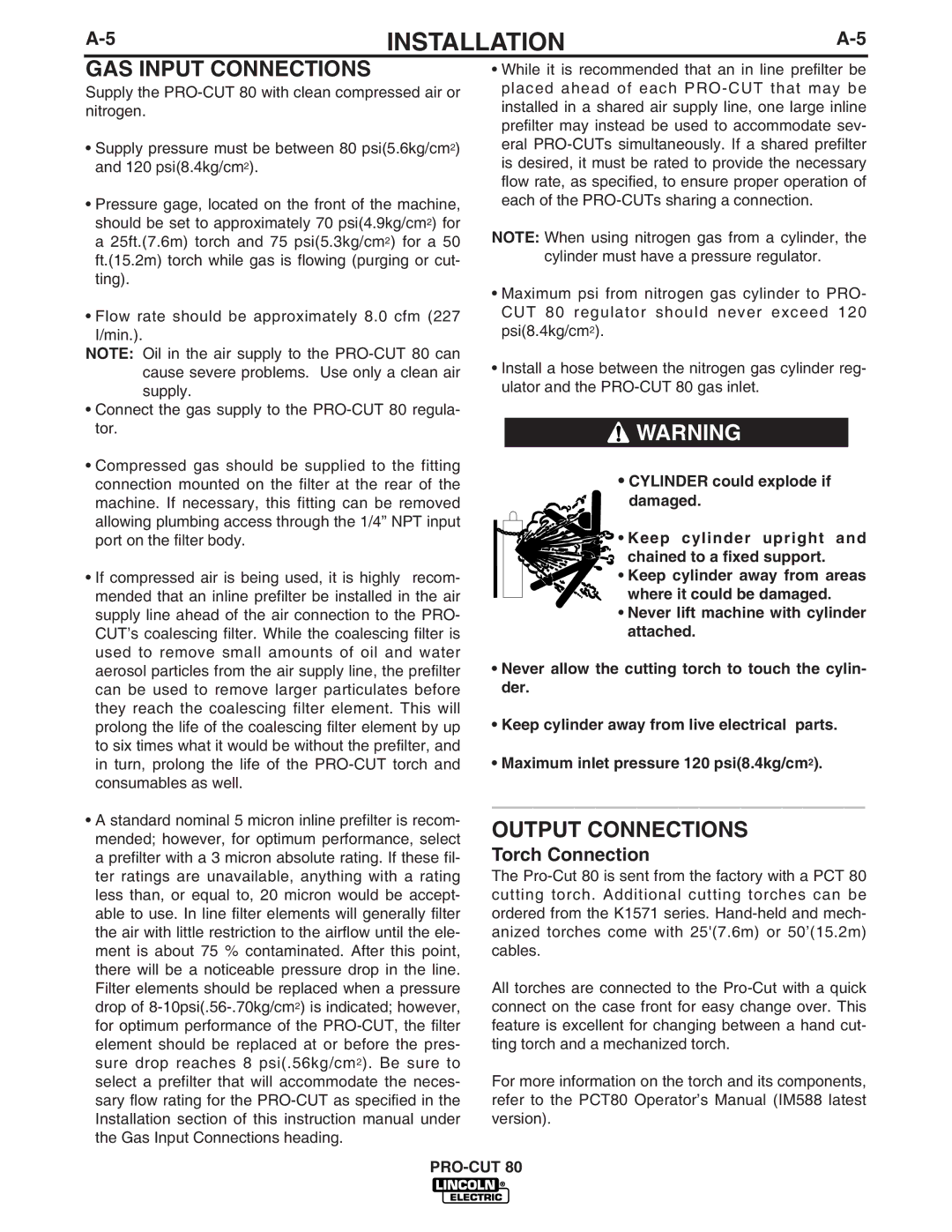
•CYLINDER could explode if
damaged.
![]()
![]() • Keep cylinder upright and
• Keep cylinder upright and
chained to a fixed support.
• Keep cylinder away from areas where it could be damaged.
•Never lift machine with cylinder attached.
•Never allow the cutting torch to touch the cylin- der.
•Keep cylinder away from live electrical parts.
•Maximum inlet pressure 120 psi(8.4kg/cm2).
__________________
OUTPUT CONNECTIONS
Torch Connection
The
All torches are connected to the
For more information on the torch and its components, refer to the PCT80 Operator’s Manual (IM588 latest version).