INSTALLATION | ||
|
|
|
FRAME GROUNDING
The frame of the
ed. A ground terminal marked ![]() is mounted on the case bottom directly behind the input power switch for this purpose. The cable that is sent attached to the machine is connected to this ground terminal. See the National Electric Code for details on proper grounding methods. Install in accordance with all local and national electrical codes.
is mounted on the case bottom directly behind the input power switch for this purpose. The cable that is sent attached to the machine is connected to this ground terminal. See the National Electric Code for details on proper grounding methods. Install in accordance with all local and national electrical codes.
INPUT VOLTAGE RECONNECTION PROCEDURE
When changing input voltages, it is necessary to change the settings behind the access door on the side of the machine. Failure to do so may result in damage to the machine.
To reconnect the
1.Open the access door on the back of the machine.
2.For 200 to 230 : Position the large switch to
For 400 to 460 : Position the large switch to
For 550 to 575 : Position the large switch to
3.Move the "A" lead to the appropriate terminal.
USE ON ENGINE DRIVEN POWER SUPPLIES
The
AC Wave Form Restrictions
The
The AC wave form frequency is between 45 and 65 Hz.
For 200 - 230 VAC Supplies:
The AC wave form peak voltage must be below 420 volts.
The RMS voltage must be 230VAC +/- 15%.
*The 230 VAC auxiliaries of Lincoln engine drives meet these conditions when run in the high idle mode.
For 380 - 415 VAC Supplies:
The AC wave form peak voltage must be below 840 volts.
The RMS voltage must be 400 VAC +/- 10%.
For 460 VAC Supplies:
The AC wave form peak voltage must be below 840 volts.
The RMS voltage of the AC wave form must be 460 VAC +/- 10%.
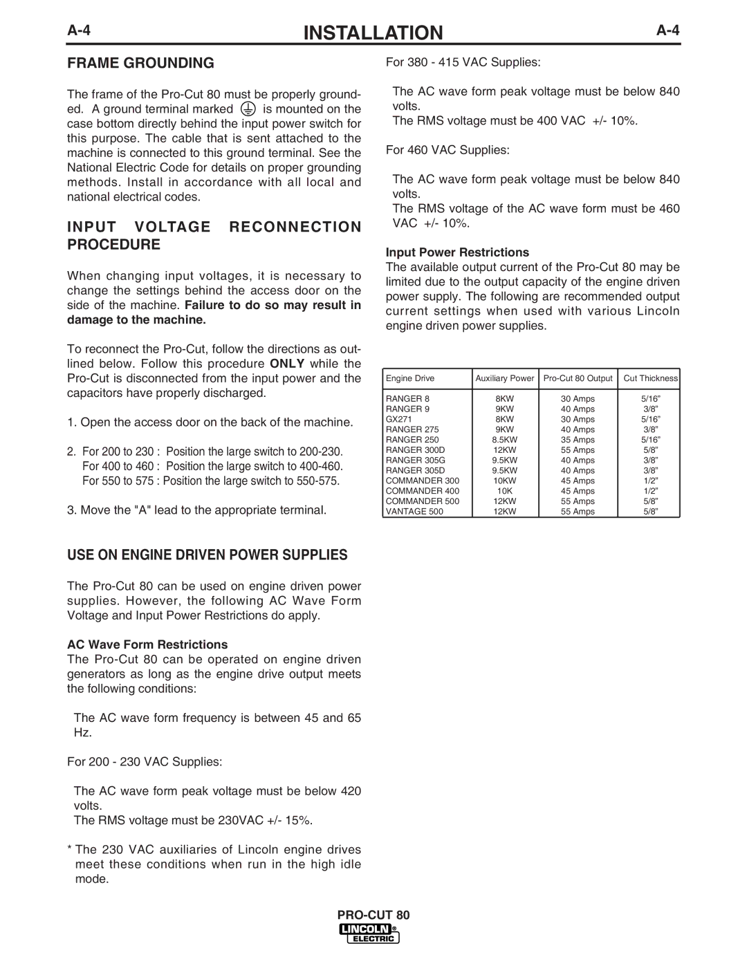
Input Power Restrictions
The available output current of the
Engine Drive | Auxiliary Power | Cut Thickness | |
|
|
|
|
RANGER 8 | 8KW | 30 Amps | 5/16” |
RANGER 9 | 9KW | 40 Amps | 3/8” |
GX271 | 8KW | 30 Amps | 5/16” |
RANGER 275 | 9KW | 40 Amps | 3/8” |
RANGER 250 | 8.5KW | 35 Amps | 5/16” |
RANGER 300D | 12KW | 55 Amps | 5/8” |
RANGER 305G | 9.5KW | 40 Amps | 3/8” |
RANGER 305D | 9.5KW | 40 Amps | 3/8” |
COMMANDER 300 | 10KW | 45 Amps | 1/2” |
COMMANDER 400 | 10K | 45 Amps | 1/2” |
COMMANDER 500 | 12KW | 55 Amps | 5/8” |
VANTAGE 500 | 12KW | 55 Amps | 5/8” |
