| OPERATION |
| ||
|
|
|
|
|
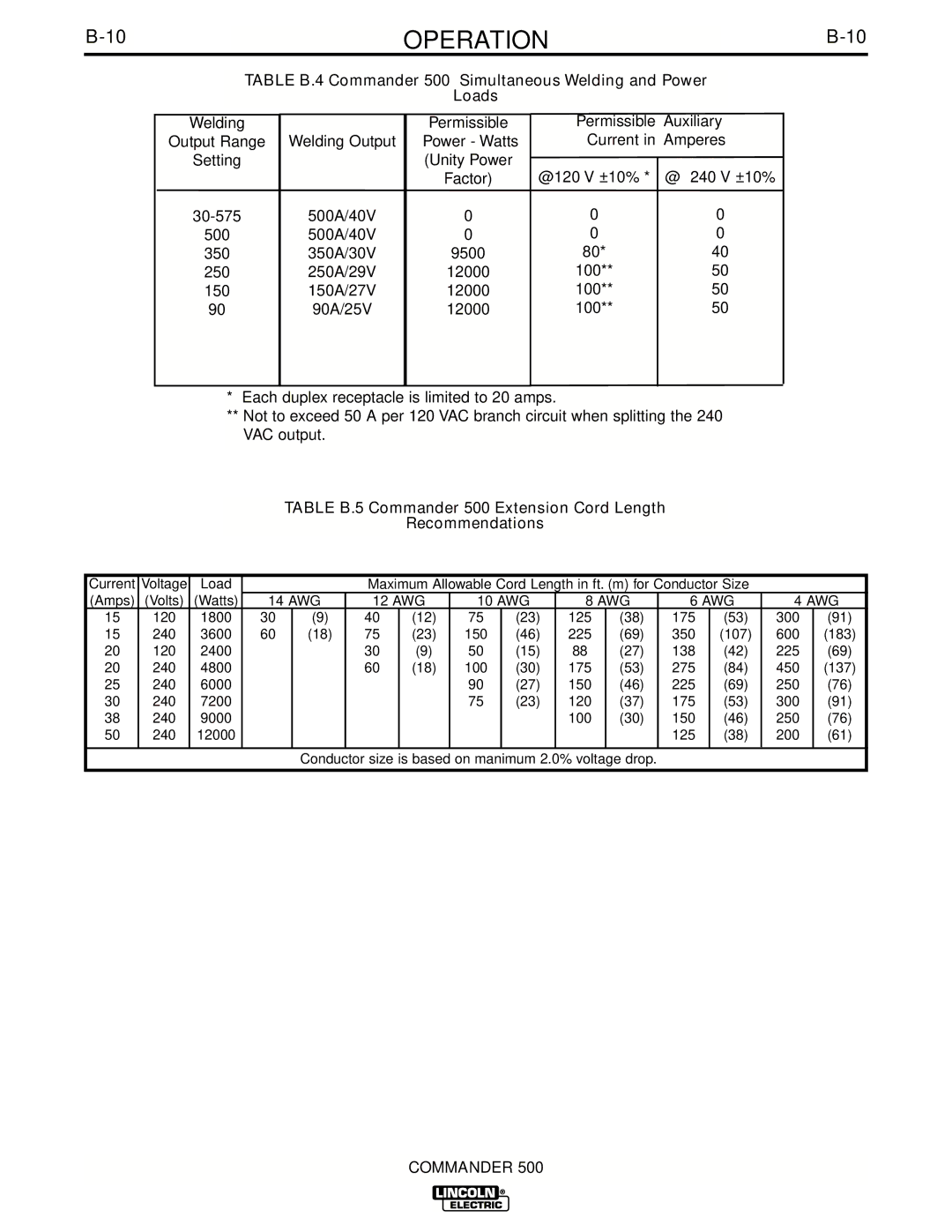
TABLE B.4 Commander 500 Simultaneous Welding and Power
Loads
Welding
Output Range
Setting
Welding Output
Permissible
Power - Watts
(Unity Power
Permissible Auxiliary Current in Amperes
500
350
250
150
90
500A/40V
500A/40V
350A/30V
250A/29V
150A/27V
90A/25V
Factor)
0
0
9500
12000
12000
12000
@120 V ±10% *
0
0
80*
100**
100**
100**
@ 240 V ±10%
0
0
40
50
50
50
*Each duplex receptacle is limited to 20 amps.
**Not to exceed 50 A per 120 VAC branch circuit when splitting the 240 VAC output.
TABLE B.5 Commander 500 Extension Cord Length
Recommendations
Current | Voltage | Load |
|
| Maximum Allowable Cord Length in ft. (m) for Conductor Size |
|
| |||||||
(Amps) | (Volts) | (Watts) | 14 AWG | 12 AWG | 10 AWG | 8 AWG | 6 AWG | 4 AWG | ||||||
15 | 120 | 1800 | 30 | (9) | 40 | (12) | 75 | (23) | 125 | (38) | 175 | (53) | 300 | (91) |
15 | 240 | 3600 | 60 | (18) | 75 | (23) | 150 | (46) | 225 | (69) | 350 | (107) | 600 | (183) |
20 | 120 | 2400 |
|
| 30 | (9) | 50 | (15) | 88 | (27) | 138 | (42) | 225 | (69) |
20 | 240 | 4800 |
|
| 60 | (18) | 100 | (30) | 175 | (53) | 275 | (84) | 450 | (137) |
25 | 240 | 6000 |
|
|
|
| 90 | (27) | 150 | (46) | 225 | (69) | 250 | (76) |
30 | 240 | 7200 |
|
|
|
| 75 | (23) | 120 | (37) | 175 | (53) | 300 | (91) |
38 | 240 | 9000 |
|
|
|
|
|
| 100 | (30) | 150 | (46) | 250 | (76) |
50 | 240 | 12000 |
|
|
|
|
|
|
|
| 125 | (38) | 200 | (61) |
|
|
|
|
|
|
|
|
|
|
|
|
|
|
|
Conductor size is based on manimum 2.0% voltage drop.
COMMANDER 500