| OPERATION |
| ||
|
|
|
|
|
For all versions, these trigger modes can be
5. THERMAL
•This status light indicates when the power source has been driven into thermal overload. If the output terminals were "ON", the "ON" light will blink indicating that the out- put will be turned back on once the unit cools down to an acceptable temperature level. If the unit was operating in the "REMOTE" mode, the trigger will need to be opened before or after the thermal has cleared and closed after the machine has cooled down to an acceptable tempera- ture to establish output.
6. CONTROL-REMOTE / LOCAL
•Two status lights indicate the location of output control as
•The LOCAL display will be lit when control is at the power source.
•The REMOTE display will be lit when a remote pot/control is detected.
These Output Control configurations can be overridden (switched) with the CONTROL push button. When changed, the unit will power up in the configuration it was in when it was last powered down.
Hidden Middle Control Panel – Process Set Up Panel
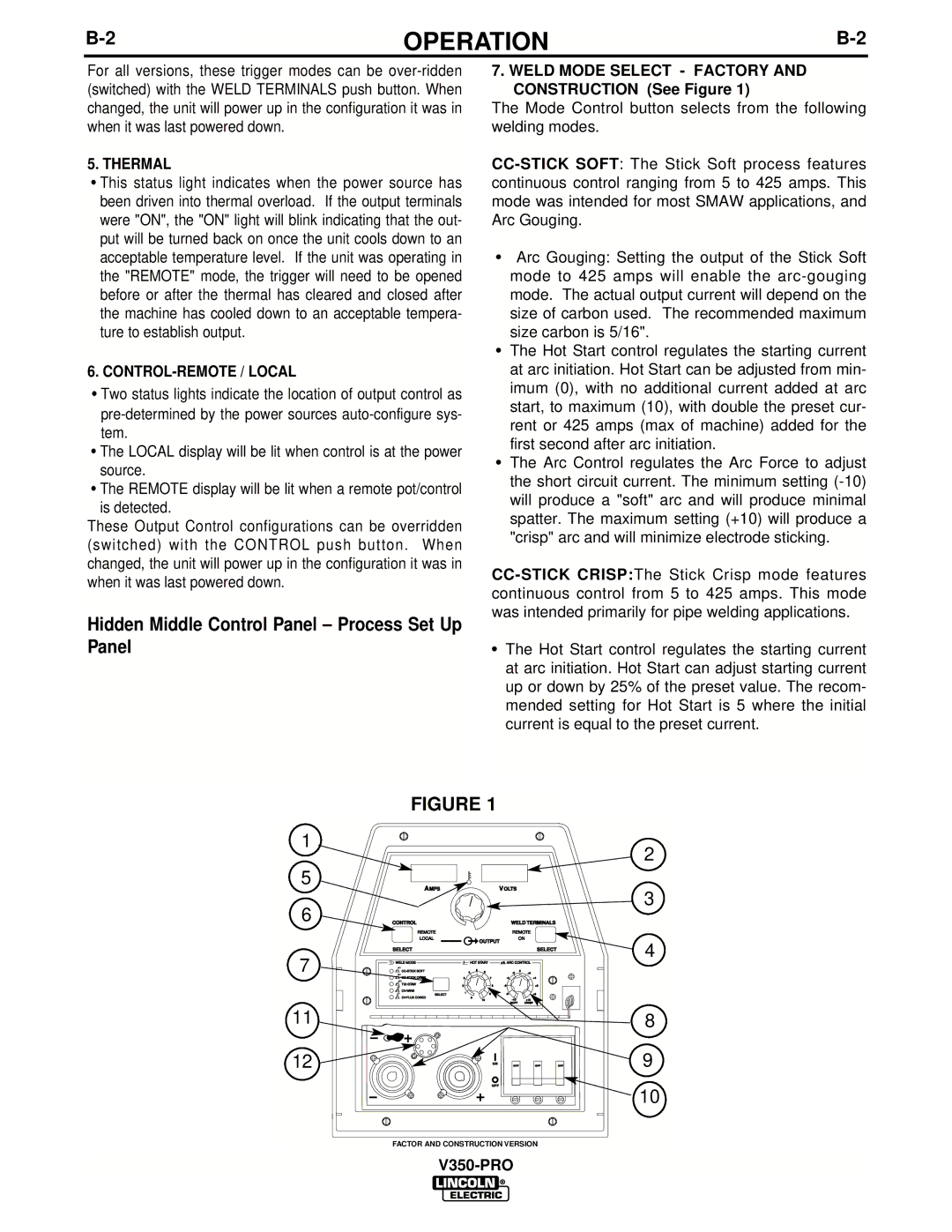
7.WELD MODE SELECT - FACTORY AND CONSTRUCTION (See Figure 1)
The Mode Control button selects from the following welding modes.
•Arc Gouging: Setting the output of the Stick Soft mode to 425 amps will enable the
•The Hot Start control regulates the starting current at arc initiation. Hot Start can be adjusted from min- imum (0), with no additional current added at arc start, to maximum (10), with double the preset cur- rent or 425 amps (max of machine) added for the first second after arc initiation.
•The Arc Control regulates the Arc Force to adjust the short circuit current. The minimum setting
•The Hot Start control regulates the starting current at arc initiation. Hot Start can adjust starting current up or down by 25% of the preset value. The recom- mended setting for Hot Start is 5 where the initial current is equal to the preset current.
1
5
6
7
11
12
FIGURE 1
AMPS | VOLTS | |
CONTROL |
| WELD TERMINALS |
REMOTE |
| REMOTE |
LOCAL | OUTPUT | ON |
|
| |
| SELECT |
|
|
|
| SELECT |
m | WELD MODE |
|
| HOT START | ARC CONTROL | |
|
| 4 | 5 | 0 | ||
|
|
| 6 | +2 | ||
|
| 3 | 7 | +4 | ||
| TIG GTAW |
| 2 | 8 | +6 | |
|
| 1 | 9 | +8 | ||
| SELECT |
| ||||
|
|
| 0 | +10 | ||
|
|
|
| 10 | ||
|
|
|
|
| SOFT | CRISP |
ON
OFF | OFF | OFF |
OFF
FACTOR AND CONSTRUCTION VERSION
2
3
4
8
9
10