| OPERATION |
| ||
|
|
|
|
|
7A. ADVANCED PROCESS PANEL
(See Figure 2)
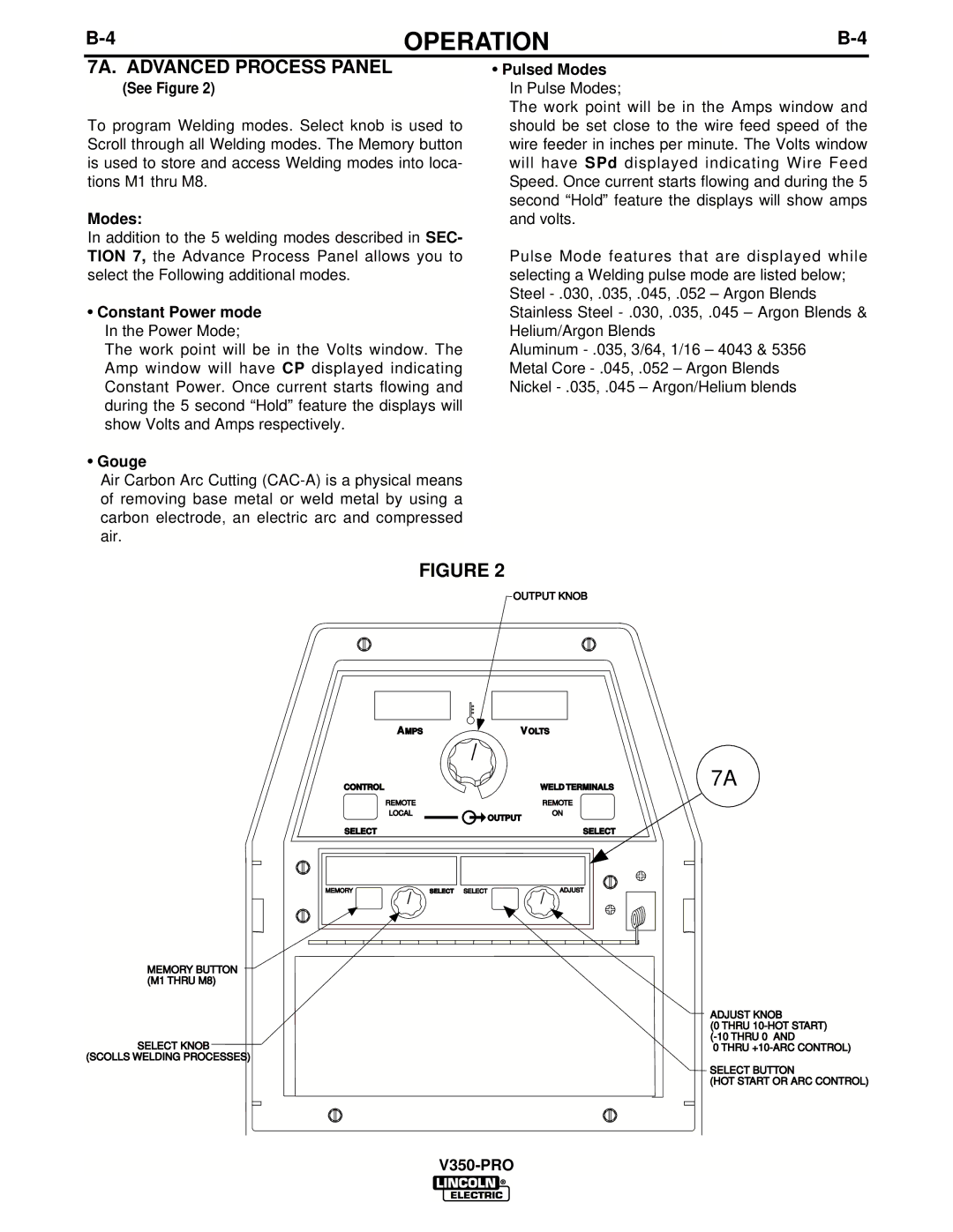
To program Welding modes. Select knob is used to Scroll through all Welding modes. The Memory button is used to store and access Welding modes into loca- tions M1 thru M8.
Modes:
In addition to the 5 welding modes described in SEC- TION 7, the Advance Process Panel allows you to select the Following additional modes.
•Constant Power mode In the Power Mode;
The work point will be in the Volts window. The Amp window will have CP displayed indicating Constant Power. Once current starts flowing and during the 5 second “Hold” feature the displays will show Volts and Amps respectively.
•Gouge
Air Carbon Arc Cutting
•Pulsed Modes In Pulse Modes;
The work point will be in the Amps window and should be set close to the wire feed speed of the wire feeder in inches per minute. The Volts window will have SPd displayed indicating Wire Feed Speed. Once current starts flowing and during the 5 second “Hold” feature the displays will show amps and volts.
Pulse Mode features that are displayed while selecting a Welding pulse mode are listed below; Steel
Aluminum
MEMORY BUTTON (M1 THRU M8)
SELECT KNOB
(SCOLLS WELDING PROCESSES)
FIGURE 2
OUTPUT KNOB
AMPS | VOLTS | |
CONTROL |
| WELD TERMINALS |
REMOTE |
| REMOTE |
LOCAL | OUTPUT | ON |
|
| |
SELECT |
|
| SELECT |
MEMORY | SELECT | SELECT | ADJUST |
7A
ADJUST KNOB
(0 THRU
0 THRU
SELECT BUTTON
(HOT START OR ARC CONTROL)
