| INSTALLATION |
| ||
|
|
|
|
|
SAFETY PRECAUTIONS
![]() WARNING
WARNING
ELECTRIC SHOCK can kill.
•TURN THE INPUT POWER OFF AT THE DISCONNECT SWITCH BEFORE ATTEMPTING TO CONNECT OR DIS-
CONNECT INPUT POWER LINES, OUTPUT CABLES, OR CONTROL CABLES.
•Only qualified personnel should perform this installation.
•Connect the green/yellow lead of the power cord to ground per U.S.National Electrical Code.
SELECT SUITABLE LOCATION
The Invertec
•The machine must be located where there is free cir- culation of clean air such that air movement in the back, out the sides and bottom will not be restricted.
•Dirt and dust that can be drawn into the machine should be kept to a minimum. Failure to observe these precautions can result in excessive operating temperatures and nuisance shutdown.
•Keep machine dry. Shelter from rain and snow. Do not place on wet ground or in puddles.
•DO NOT MOUNT OVER COMBUSTIBLE SURFACES.
![]() CAUTION
CAUTION
Where there is a combustible surface directly under stationary or fixed electrical equipment, that surface shall be covered with a steel plate at least
.06”(1.6mm) thick, which shall extend not less than 5.90”(150mm) beyond the equipment on all sides.
STACKING
TILTING
Place the machine directly on a secure, level surface or on a recommended undercarriage. The machine may topple over if this procedure is not followed.
INPUT AND GROUNDING CONNECTIONS
•Only a qualified electrician should connect the Invertec
•When received directly from the factory, multiple voltage machines are internally connected for 460VAC. If 460VAC is the desired input, then the machine may be connected to the power system without any setup required inside the machine.
•Initial 200VAC - 415VAC and 575VAC operation will require an Input voltage panel setup.
•Initial 200VAC - 415VAC and 575VAC operation will require an Input voltage panel setup.
•Open the access panel on the rear of the machine.
•For 200 or 230: Position the large switch to 200- 230.
For higher voltages: Position the large switch to
•Move the "A" lead to the appropriate terminal.
POWER CORD CONNECTION
A 10 ft. power cord is provided and wired into the machine. Follow the power cord connection instruc- tions.
![]() CAUTION
CAUTION
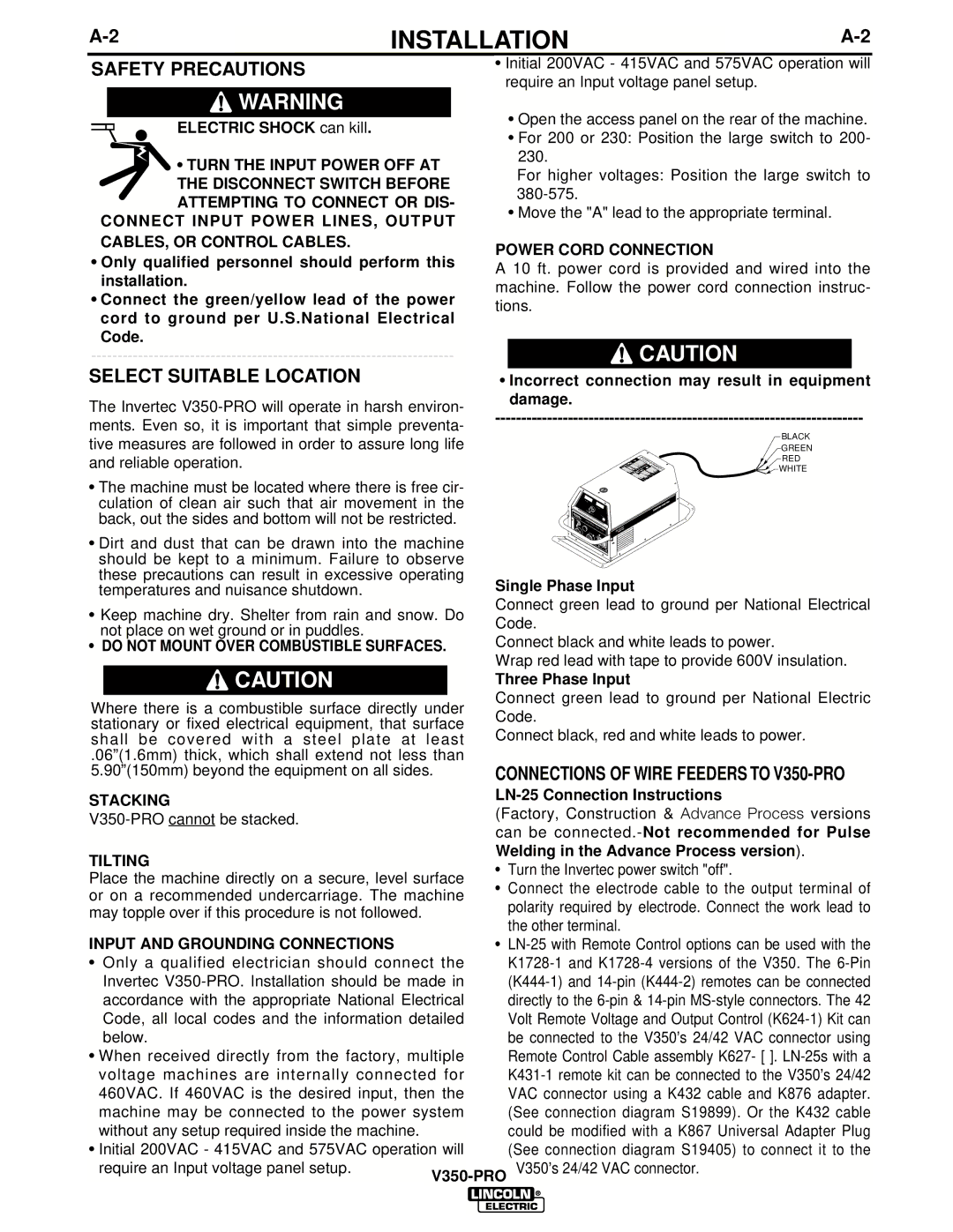
•Incorrect connection may result in equipment damage.
BLACK
GREEN
RED
![]()
![]() WHITE
WHITE
A
V
LINCOLN
ELECTRIC
I
NVERTEC V
350-
PRO
Single Phase Input
Connect green lead to ground per National Electrical Code.
Connect black and white leads to power.
Wrap red lead with tape to provide 600V insulation.
Three Phase Input
Connect green lead to ground per National Electric Code.
Connect black, red and white leads to power.
CONNECTIONS OF WIRE FEEDERS TO V350-PRO
LN-25 Connection Instructions
(Factory, Construction & Advance Process versions can be
•Turn the Invertec power switch "off".
•Connect the electrode cable to the output terminal of polarity required by electrode. Connect the work lead to the other terminal.
•
V350’s 24/42 VAC connector.