INSTALLATION |
3.Route the cable under and around the back of the Wire Feed Gearbox (6).
4.For GMAW Only: Refer to Figure A.2. As deliv- ered, the welder is wired for positive polarity. This is the appropriate configuration for the Gas Metal Arc Welding (GMAW) process. To complete instal- lation, use the provided wing nut to connect the work cable’s terminal lug to the negative
(6). Make sure that both wing nuts are tight.
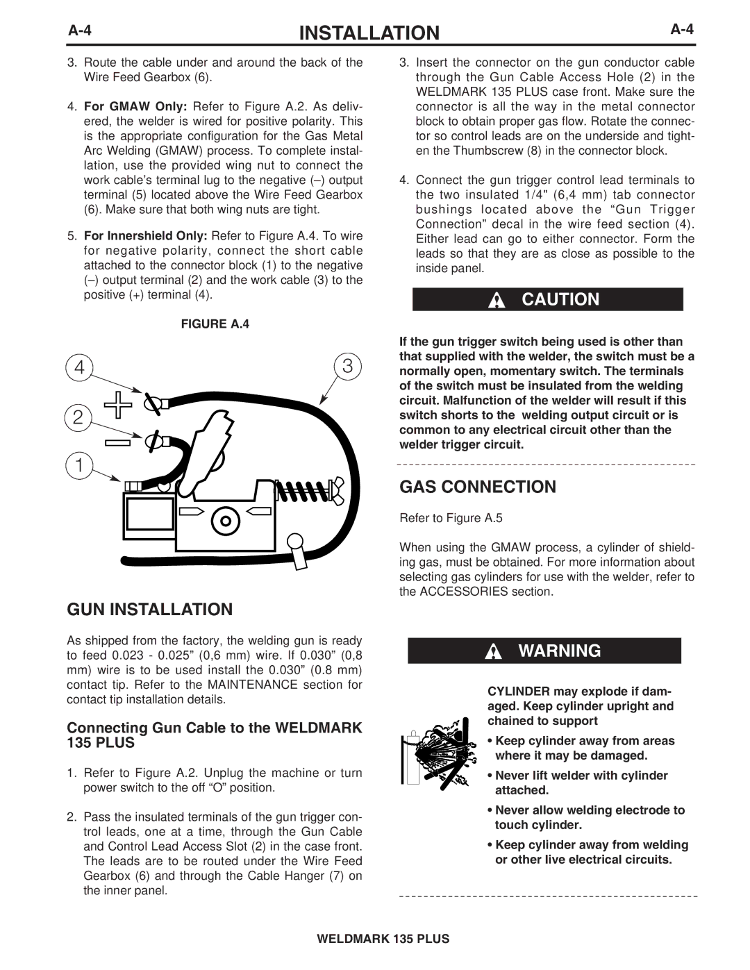
5.For Innershield Only: Refer to Figure A.4. To wire for negative polarity, connect the short cable attached to the connector block (1) to the negative
| FIGURE A.4 |
4 | 3 |
2
1
GUN INSTALLATION
As shipped from the factory, the welding gun is ready to feed 0.023 - 0.025” (0,6 mm) wire. If 0.030” (0,8
mm)wire is to be used install the 0.030” (0.8 mm) contact tip. Refer to the MAINTENANCE section for contact tip installation details.
Connecting Gun Cable to the WELDMARK 135 PLUS
1.Refer to Figure A.2. Unplug the machine or turn power switch to the off “O” position.
2.Pass the insulated terminals of the gun trigger con- trol leads, one at a time, through the Gun Cable and Control Lead Access Slot (2) in the case front. The leads are to be routed under the Wire Feed Gearbox (6) and through the Cable Hanger (7) on the inner panel.
3.Insert the connector on the gun conductor cable through the Gun Cable Access Hole (2) in the WELDMARK 135 PLUS case front. Make sure the connector is all the way in the metal connector block to obtain proper gas flow. Rotate the connec- tor so control leads are on the underside and tight- en the Thumbscrew (8) in the connector block.
4.Connect the gun trigger control lead terminals to the two insulated 1/4" (6,4 mm) tab connector bushings located above the “Gun Trigger Connection” decal in the wire feed section (4). Either lead can go to either connector. Form the leads so that they are as close as possible to the inside panel.
CAUTION
If the gun trigger switch being used is other than that supplied with the welder, the switch must be a normally open, momentary switch. The terminals of the switch must be insulated from the welding circuit. Malfunction of the welder will result if this switch shorts to the welding output circuit or is common to any electrical circuit other than the welder trigger circuit.
GAS CONNECTION
Refer to Figure A.5
When using the GMAW process, a cylinder of shield- ing gas, must be obtained. For more information about selecting gas cylinders for use with the welder, refer to the ACCESSORIES section.
WARNING
CYLINDER may explode if dam- aged. Keep cylinder upright and chained to support
• Keep cylinder away from areas where it may be damaged.
• Never lift welder with cylinder attached.
•Never allow welding electrode to touch cylinder.
•Keep cylinder away from welding or other live electrical circuits.
WELDMARK 135 PLUS