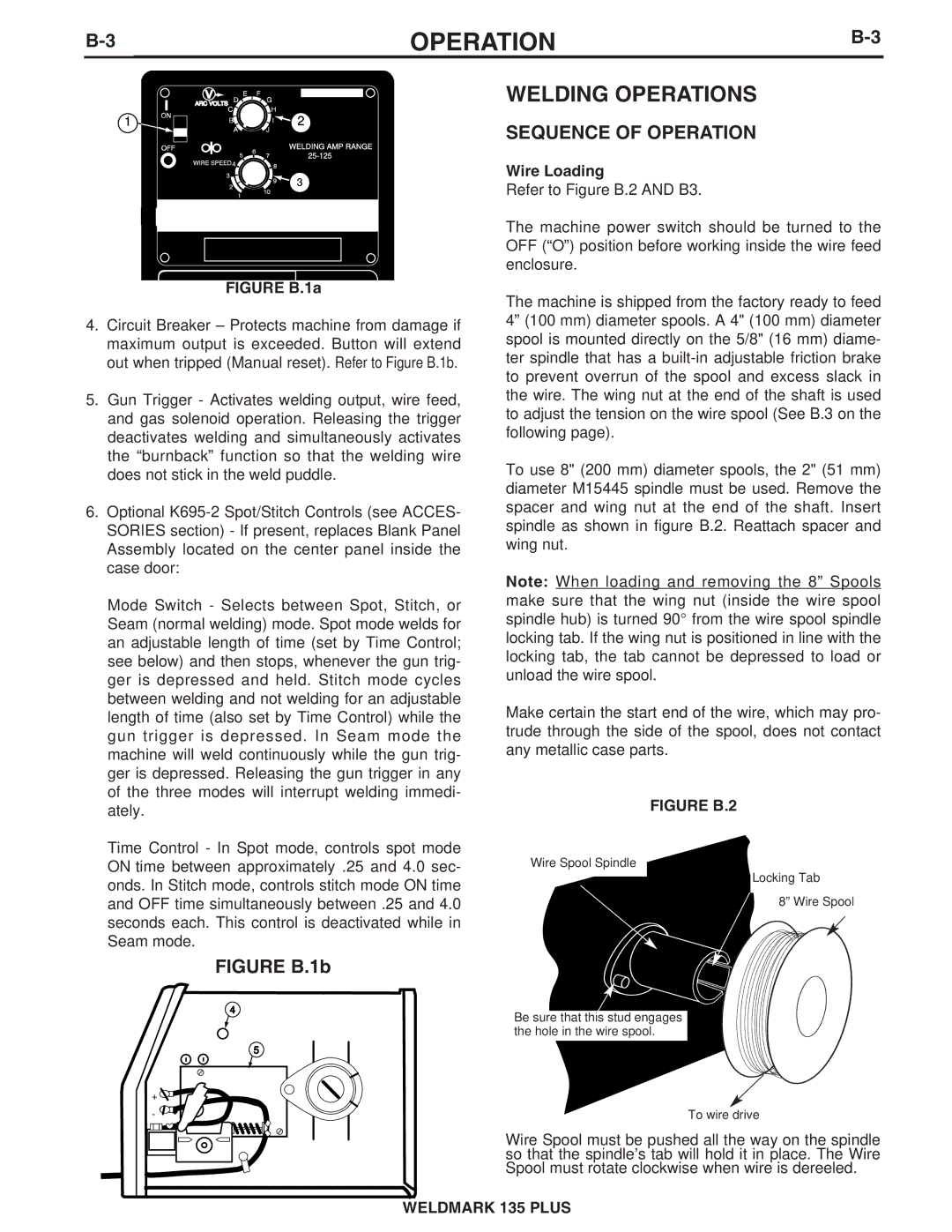
|
| OPERATION | |
1 | 2 |
WELDING AMP RANGE
3
FIGURE B.1a
4.Circuit Breaker – Protects machine from damage if maximum output is exceeded. Button will extend out when tripped (Manual reset). Refer to Figure B.1b.
5.Gun Trigger - Activates welding output, wire feed, and gas solenoid operation. Releasing the trigger deactivates welding and simultaneously activates the “burnback” function so that the welding wire does not stick in the weld puddle.
6.Optional
Mode Switch - Selects between Spot, Stitch, or Seam (normal welding) mode. Spot mode welds for an adjustable length of time (set by Time Control; see below) and then stops, whenever the gun trig- ger is depressed and held. Stitch mode cycles between welding and not welding for an adjustable length of time (also set by Time Control) while the gun trigger is depressed. In Seam mode the machine will weld continuously while the gun trig- ger is depressed. Releasing the gun trigger in any of the three modes will interrupt welding immedi- ately.
Time Control - In Spot mode, controls spot mode ON time between approximately .25 and 4.0 sec- onds. In Stitch mode, controls stitch mode ON time and OFF time simultaneously between .25 and 4.0 seconds each. This control is deactivated while in Seam mode.
FIGURE B.1b
4
5
+ ![]()
![]()
- ![]()
WELDING OPERATIONS
SEQUENCE OF OPERATION
Wire Loading
Refer to Figure B.2 AND B3.
The machine power switch should be turned to the OFF (“O”) position before working inside the wire feed enclosure.
The machine is shipped from the factory ready to feed 4” (100 mm) diameter spools. A 4" (100 mm) diameter spool is mounted directly on the 5/8" (16 mm) diame- ter spindle that has a
To use 8" (200 mm) diameter spools, the 2" (51 mm) diameter M15445 spindle must be used. Remove the spacer and wing nut at the end of the shaft. Insert spindle as shown in figure B.2. Reattach spacer and wing nut.
Note: When loading and removing the 8” Spools make sure that the wing nut (inside the wire spool spindle hub) is turned 90° from the wire spool spindle locking tab. If the wing nut is positioned in line with the locking tab, the tab cannot be depressed to load or unload the wire spool.
Make certain the start end of the wire, which may pro- trude through the side of the spool, does not contact any metallic case parts.
FIGURE B.2
Wire Spool Spindle
Locking Tab
8” Wire Spool
Be sure that this stud engages the hole in the wire spool.
To wire drive
Wire Spool must be pushed all the way on the spindle so that the spindle’s tab will hold it in place. The Wire Spool must rotate clockwise when wire is dereeled.
WELDMARK 135 PLUS